
Page 120 - IJB-9-4
P. 120
International Journal of Bioprinting An inkjet-printed bendable antenna for wearable electronics
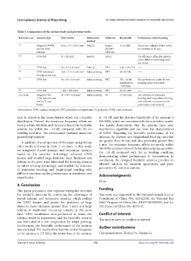
Table 3. Comparison of the current study and previous works
References no. Antenna type Dimensions Fabrication Substrate Bandwidth Performance under bending
method
[15] Integrated UWB/ 63.6 × 37 × 0.254 mm 3 Printed Rogers 2–12 GHz Tested on a cylinder with a radius
narrow-band RO3003 of curvature of 20 mm
antenna substrate
[16] CPW-fed 81 × 20 mm 2 Knitted Fabric —— The efficiency of flexible antenna
under different stretching levels
was tested
[17] CPW-fed 20 × 8.7 × 0.4 mm 3 Printed FR-4 5.15–7.29 GHz ——
[20] CPW-fed slotted 12.8 × 7.5 × 0.135 mm 3 Inkjet printing PET 26–40 GHz ——
monopole antenna
[21] CPW-fed 40 × 35 × 0.3 mm 3 Inkjet printing PET The −10 dB The performance under 40 mm
bandwidth is bending radius was tested
~530 MHz
[22] CPW-fed ~200 × 300 mm 2 Inkjet printing PET 60–65 GHz ——
Our work Integrated the 30 × 30 × 0.05 mm 3 Inkjet printing PI 2–2.85 GHz The influence of transverse
CPW-fed structure bending and longitudinal bending
and the T-type with different curvatures on the
fractal performance was studied
Abbreviations: CPW, coplanar waveguide; PET, polyethylene terephthalate; PI, polyimide; UWB, ultra-wideband
may be related to the tissue density, which has a variable is −32 dB, and the absolute bandwidth of the antenna is
distribution. Overall, the resonance frequency offsets are 850 MHz, which are consistent with the simulation results.
mostly within 360 MHz and the return loss of the bendable The results demonstrate that the antenna have anti-
antenna are within the −14 dB compared with the no interference capability and can meet the characteristics
bending condition. The performance variation meets the of UWB. Regarding the bendable performance of the
general requirements. antenna, for traverse and longitudinal bending radii that
are greater than 30 mm and skin proximity greater than
In addition, the comparison of this paper and previous
other works is shown in Table 3. In short, in this work, 1 mm, the resonance frequency offsets are mostly within
360 MHz and return loss of the bendable antenna are within
we integrated fractal antenna and serpentine antenna the −14 dB compared with the no bending condition,
based on the meander technology; achieved UWB demonstrating robust performance in transmission. In
feature and avoided large dielectric layer thickness and conclusion, the designed bendable antenna provides an
volume at the same time; fabricated the bending antenna effective solution for wearable applications and next-
by inkjet printing technology; and studied the influence generation 5G communications.
of transverse bending and longitudinal bending with
different curvature on the performance in simulation and Acknowledgments
experiments.
None.
4. Conclusion
This paper proposes a new coplanar waveguide structure Funding
for bendable antennas by combining the advantages of This work was supported by the National Natural Science
fractal antenna and serpentine antenna, which realizes Foundation of China (No. 82102230), the National Key
the UWB feature and avoids the problems of large R&D Program of China (No. 2018YFE0205000), and the
dielectric layer thickness (greater than 1 mm) and large 111 Project of China (No. B07014).
volume of traditional microstrip antenna at the same
time. HFSS simulations were performed to obtain the Conflict of interest
optimal structure parameters, and the bendable antenna The authors have no conflicts of interest.
was fabricated at a low temperature by inkjet printing.
Furthermore, the bendable performance of the antenna Author contributions
was evaluated. The results show that the central frequency
of the antenna is 2.5 GHz, the return loss of the antenna Conceptualization: Zhihua Pu, Dachao Li
Volume 9 Issue 4 (2023) 112 https://doi.org/10.18063/ijb.722