
Page 119 - IJB-9-4
P. 119
International Journal of Bioprinting An inkjet-printed bendable antenna for wearable electronics
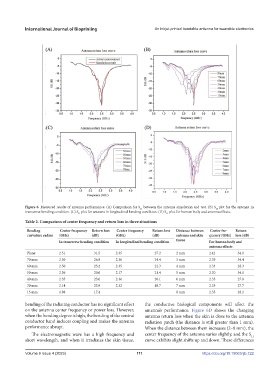
Figure 6. Measured results of antenna performance. (A) Comparison for S between the antenna simulation and test. (B) S plot for the antenna in
11
11
transverse bending condition. (C) S plot for antenna in longitudinal bending condition. (D) S plot for human body and antenna effects.
11 11
Table 2. Comparison of center frequency and return loss in three situations
Bending Center frequency Return loss Center frequency Return loss Distance between Center fre- Return
curvature radius (GHz) (dB) (GHz) (dB) antenna and skin quency (GHz) loss (dB)
In transverse bending condition In longitudinal bending condition tissue For human body and
antenna effects
Plane 2.51 −31.5 2.35 −27.2 2 mm 2.42 −34.0
70 mm 2.50 −26.8 2.36 −24.4 3 mm 2.39 −34.4
60 mm 2.50 −23.2 2.35 −22.3 4 mm 2.33 −28.3
50 mm 2.36 −20.6 2.17 −21.4 5 mm 2.30 −34.1
40 mm 2.35 −23.0 2.36 −20.1 6 mm 2.35 −27.8
30 mm 2.14 −23.9 2.32 −18.7 7 mm 2.35 −27.7
15 mm 1.88 −17.4 8 mm 2.35 −28.2
bending of the radiating conductor has no significant effect the conductive biological components will affect the
on the antenna center frequency or power loss. However, antenna’s performance. Figure 6D shows the changing
when the bending degree is high, the bending of the central antenna return loss when the skin is close to the antenna
conductor band induces coupling and makes the antenna radiation patch (the distance is still greater than 1 mm).
performance abrupt. When the distance between them increases (2–8 mm), the
The electromagnetic wave has a high frequency and center frequency of the antenna varies slightly, and the S
11
short wavelength, and when it irradiates the skin tissue, curve exhibits slight shifts up and down. These differences
Volume 9 Issue 4 (2023) 111 https://doi.org/10.18063/ijb.722