
Page 114 - IJB-9-4
P. 114
International Journal of Bioprinting An inkjet-printed bendable antenna for wearable electronics
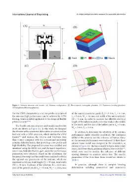
Figure 1. Antenna structure and models. (A) Antenna configuration. (B) Three-layered rectangular phantom. (C) Transverse bending phantom.
(D) Longitudinal bending phantom.
For the UWB characteristics and low-profile structure of of the central conductor patch (L ) = 9 mm, L = 6 mm,
s
3
the antenna, high performance can be achieved by CPW L = 8 mm, W = 14 mm, and width of the antenna feeder
1
1
feeding, which is widely applicable to the design of flexible (S) = 4 mm. In order to increase the effective electrical
printed circuits [23,24] . length of the radiation patch, a slot was made in the middle
of the patch, and the size of the hollow part is L = 6 mm,
The flexible antenna structure and models used in this 8
study are shown in Figure 1A. In this work, we designed W = 2 mm, L = 3 mm.
8
7
the vibrator with a symmetric bifurcation structure and the In addition, to determine the reliability of the antenna
feed end with a CPW structure, which enables the UWB performance under wearable conditions, the conformal
feature and reduces the volume and thickness (less ability of the antenna and the influence of human tissue
[25]
than 1 mm) compared with the conventional microstrip on the antenna performance were evaluated. A three-layer
antenna dielectric layers, thus providing a low profile and cubical tissue model was designed in the simulation, as
high flexibility. The proposed structure was modeled and shown in Figure 1B. The tissue model includes skin (2 mm
simulated using the HFSS tool, and the input impedance, thick), fat (10 mm thick), and muscle layers (28 mm thick) ,
[27]
return loss, field distribution, gain, and other performance which were used to analyze the influence of different
parameters were obtained. Based on the simulation, the spacing distances on antenna return loss. The specific
frequency was swept and the results were analyzed to obtain parameters of the three-layer tissue model are shown in
the optimal size parameters of the antenna, which are Table 1.
expressed as follows: total length (L) = 30 mm, total width
(W) = 30 mm, thickness of the substrate (h) = 0.05 mm, In practice, although there is complex bending
area of the ground patch (L ) = 8 mm, W = 11 mm, area deformation including symmetrical and asymmetry
p
p
Volume 9 Issue 4 (2023) 106 https://doi.org/10.18063/ijb.722