
Page 455 - IJB-9-5
P. 455
International Journal of Bioprinting 3D-printed oblique lumbar interbody cage
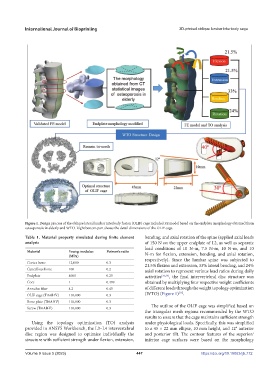
Figure 1. Design process of the oblique lateral lumbar interbody fusion (OLIF) cage included FE model based on the endplate morphology obtained from
osteoporosis in elderly and WTO. Right bottom part shows the detail dimensions of the OLIF cage.
Table 1. Material property simulated during finite element bending, and axial rotation of the spine (applied axial loads
analysis of 150 N on the upper endplate of L2, as well as separate
load conditions of 10 N-m, 7.5 N-m, 10 N-m, and 10
Material Young modulus Poisson’s ratio N-m for flexion, extension, bending, and axial rotation,
(MPa)
Cortex bone 12,000 0.3 respectively). Since the lumbar spine was subjected to
21.5% flexion and extension, 33% lateral bending, and 24%
Cancellous bone 100 0.2 axial rotation to represent various load ratios during daily
Endplate 4000 0.25 activities [23,24] , the final intervertebral disc structure was
Core 1 0.499 obtained by multiplying four respective weight coefficients
Annulus fiber 4.2 0.45 of different loads through the weight topology optimization
[16]
OLIF cage (Ti6Al4V) 110,000 0.3 (WTO) (Figure 1) .
Bone plate (Ti6Al4V) 110,000 0.3
Screw (Ti6Al4V) 110,000 0.3 The outline of the OLIF cage was simplified based on
the triangular mesh regions recommended by the WTO
results to ensure that the cage maintains sufficient strength
Using the topology optimization (TO) analysis under physiological loads. Specifically, this was simplified
provided in ANSYS Workbench, the L3–L4 intervertebral to a 45 × 22 mm ellipse, 10 mm height, and 12° anterior
disc region was designed to optimize individually the and posterior tilt. The contour features of the superior/
structure with sufficient strength under flexion, extension, inferior cage surfaces were based on the morphology
Volume 9 Issue 5 (2023) 447 https://doi.org/10.18063/ijb.772