
Page 456 - IJB-9-5
P. 456
International Journal of Bioprinting 3D-printed oblique lumbar interbody cage
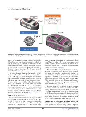
Figure 2. The YM lattice was designed with a spherical structure (pillar diameter of Ø 0.3 mm) and arranged in the hollow part of the oblique lateral lumbar
interbody fusion (OLIF) cage. The porosity of each lattice was set to 65%, and the pore size was set at 600–900 μm.
counted by previous osteoporosis patients. Two threaded screws (5.5 mm in diameter and 40 mm in length) placed
oblique holes were established on the superior and inferior in the L3 and L4 bodies with a lateral fixation plate (noted
surfaces of the cage to facilitate the insertion of fixation as CLS). All three models underwent FE simulations to
screws. To obtain the best screw fixation strength and avoid understand the mechanical responses between different
screw loosening, two screws were placed 30° up and down implant combinations (Figure 3).
the transverse plane and staggered at 40° angles anteriorly Three models of CA, CES, and CLS were meshed using
and posteriorly (Figure 1). quadratic ten-node tetrahedral structural solid elements,
To reduce the stress-shielding effect caused by the high with their corresponding eminent/node numbers of
elastic modulus and increase the bone fusion efficiency 464762/723280, 442500/740485, and 513566/809520,
of the OLIF cage, the peripheral region wall thickness, respectively. The Ti6Al4V was assigned as the material
bone fusion groove contours, and that around the screw property for the cage, screw, and lateral fixation plate.
hole of the cage were set 2, 1.5, and 1 mm, respectively. Other material properties and loading and boundary
The bone fusion groove was filled and randomly arranged conditions were the same with previous section of FE
in a SU(N ) Yang-Ming (YM) lattice, which was designed model generation and validation.
c
as a multi-corner spherical structure for excepting cell The ROM between L3 and L4 and stress distribution at
clustering with a 1-mm unit cube and a pillar diameter the superior endplate of the L4 was recorded to evaluate the
3
of Ø 0.3 mm. The porosity of each lattice was set to 65%, stability of different fixation systems. ROM was defined as
and pore size was controlled at a range of 600–900 μm the variation of the rotation angle of the adjacent lumbar
according to literatures’ suggestion (Figure 2) [11,12,25] .
vertebral bodies. The rotation angle of a single vertebral body
was obtained by calculating the dot production of a fixed
2.3. Finite element analysis vector, which was formed by the same two feature points
Three simulated models included depending on where the within the vertebral body, before and after simulations.
OLIF cage was implanted: (i) along the L3–L4 disc (noted
as CA), (ii) in the L3-L4 disc with two screws embedded 2.4. OLIF cage 3D printing and functional fatigue test
in L3 and L4 (5.5 mm in diameter and 40 mm in length; The OLIF cage randomly filled with YM lattice in the bone
noted as CES), and (iii) in the L3–L4 disc and two lateral fusion grooves was fabricated using a metal 3D printer
Volume 9 Issue 5 (2023) 448 https://doi.org/10.18063/ijb.772