
Page 534 - IJB-9-6
P. 534
International Journal of Bioprinting High-performance SrCS scaffolds via vat photopolymerization
(based on powders) were added into HDDA and stirred energy of 9, 20, 28, and 32 mJ/cm to obtain the green
2
for 2 min. Then, ceramic powders were added and stirred bodies, respectively. Finally, the printed green bodies were
at 2000 r/min for 5 min in a vacuum planetary stirring debinded and sintered to obtain the composite bioceramic
defoaming machine (SIE-MIX80, Guangzhou SIENOX, scaffolds (detailed steps shown in Figure 5a and b).
Technology Co., LTD., China). Then, zirconia mill balls
were added and stirred at 1200 r/min for another 25 min. 2.3. In vitro immersion experiment
Finally, the ceramic suspension with a solid loading of To assess the biodegradability of the scaffolds, the SrCS-
40 vol.% was obtained. The gyroid type TPMS structure BTA scaffolds were immersed in SBF (pH = 7.4) at 37°C
can be modeled by MATLAB software according to the in a shaker for 4, 7, and 14 days, respectively. The ratio of
following parametric Equation I : scaffold mass to solution volume was set as 1 g: 100 mL.
[34]
Finally, the scaffolds were cleaned with deionized water and
2 2 2 2 dried at 37°C for 24 h. The mass of the degraded scaffolds
sin x cos y sin y cos z was measured by a precision electronic balance (ME403,
a a a a (I) METTLER TOLEDO, Switzerland). The degradation rates
sin 2 2 t were calculated using Equation III:
x
z cos
a a D % 100 W W / W 1 (III)
2
1
r
where a is the cubic cell length, and t controls the volume
enclosed by the surface of TPMS. The side length of the where D is the degradation rate of the scaffold, and W
r
1
cubic gyroid structural model was 10 mm, and the porosity and W are the mass before and after immersion in SBF
2
was 66% (a = 1.25 mm, t = 0.48). Then, the model was sliced solution, respectively.
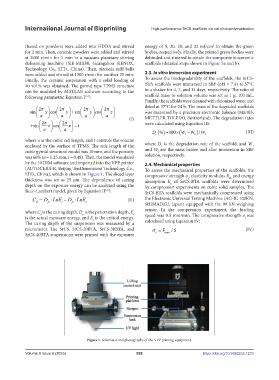
by the 10 DIM software and imported into the VPP printer 2.4. Mechanical properties
(AUTOCERA-R, Beijing TenDimensions Technology Co., To assess the mechanical properties of the scaffolds, the
LTD., China), which is shown in Figure 1. The sliced layer compressive strength σ , elasticity modulus E and energy
thickness was set as 25 μm. The dependence of curing absorption E of SrCS-BTA scaffolds were determined
m,
c
depth on the exposure energy can be analyzed using the by compression experiments on cubic solid samples. The
a
Beer–Lambert model, given by Equation II : SrCS-BTA scaffolds were mechanically compressed using
[35]
C D Ln E D Ln E (II) the Electronic Universal Testing Machine (AG-IC 100KN,
p
p
i
c
d
SHIMADZU, Japan) equipped with the 90 kN weighing
where C is the curing depth, D is the penetration depth, E i sensor. In the compression experiment, the loading
d
p
is the actual exposure energy, and E is the critical energy. speed was 0.5 mm/min. The compressive strength σ was
c
c
The curing depth of the suspension was measured by a calculated using Equation IV:
micrometer. The SrCS, SrCS-20BTA, SrCS-30BTA, and F S / (IV)
SrCS-40BTA suspensions were printed with the exposure c max
Figure 1. Schematic and photography of the VPP printing equipment.
Volume 9 Issue 6 (2023) 526 https://doi.org/10.36922/ijb.1233