
Page 185 - v11i4
P. 185
International Journal of Bioprinting Design of SLM-Ta artificial vertebral body
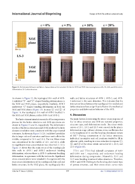
Figure 11. Deformation behavior and failure characteristics of the tantalum LS-3 in the XOZ and YOZ observation planes at 0%, 5%, 10%, and 20% strains.
Abbreviation: LS: Lattice structure.
As shown in Figure 12, the topological thin-wall of AVB- walls and lattice structures of AVB-1, AVB-2, and AVB-
1 exhibited “S”- and “C”-shaped bending deformations in 3 deformed in the same direction. This indicates that the
the XOZ and YOZ planes, respectively. Similarly, AVB-2 interaction forces between the topological thin-walled and
underwent “C”-shaped bending deformation in both the lattice structures have a significant effect on the mechanical
XOZ and YOZ planes (Figure 13). In areas ① and ② of properties and deformation behavior of the AVB.
Figure 14, the topological thin wall of AVB-3 buckled in
the XOZ and YOZ planes, unlike AVB-1 and AVB-2. 4. Discussion
The finite-element simulation results of the compression The main factors determining the stress–strain response of
process for the lattice structures and AVB specimens are the Ta lattice structure and AVB are material properties,
shown in Figures 15 and 16, respectively. The deformation structure type, and deformation mode. The stress–strain
modes of the lattice structures and AVBs predicted by finite curves of LS-1, LS-2, and LS-3 were smooth in the plastic
element simulation were consistent with the experimental deformation stage without obvious stress oscillations due
outcomes. As shown in Figure 15, LS-1 exhibited instability to the toughness of Ta and the bending-dominated nature
53
due to larger sidewall curvature and fewer unit cells in the of ISS. During compression of the lattice structures,
middle, compared to LS-2 and LS-3. The von Mises stress individual incomplete unit cell positions tended to fill in
was concentrated in the middle of LS-1 and LS-2, while adjacent voids, resulting in stress reduction in regions ①,
no significant stress concentration was observed in LS-3. ②, and ③ of the stress–strain curves for LS-1, LS-2, and
Figure 16 shows that the main struts of the topologically LS-3 (Figure 6B).
thin walls in AVB-1 and AVB-2 underwent bending TTS-1 and TTS-2 had sidewall curvatures of 0.027
deformation, whereas those in AVB-3 underwent buckling and 0.014 mm , respectively, and underwent bending
−1
deformation, in agreement with the test results. Significant deformation during compression. Meanwhile, LS-1 and
stress concentrations were revealed in the regions with the LS-2 were bending-dominant lattice structures. Therefore,
most severe deformations of the topologically thin wall and AVB-1 and AVB-2 belong to the bending-dominated type
lattice structure. In the YOZ plane, the topologically thin of porous structure, and their stress–strain curves were
Volume 11 Issue 4 (2025) 177 doi: 10.36922/IJB025150133