
Page 420 - v11i4
P. 420
International Journal of Bioprinting Swelling–shrinking behavior of hydrogel
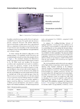
Figure 1. A high-precision 3D printing device with controllable humidity in the printing space.
humidity-controlled enclosure and the 3D print head, were mesh, auto-generated by COMSOL, comprised 14,090
excluded from the analysis. During the material extrusion domain elements.
process, continuous filaments with uniform diameters To estimate the swelling–shrinking behavior of
were extruded from a circular nozzle. Due to gravitational hydrogel filaments, a moving mesh was employed in the
effects, a compressive deformation occurred at the bottom FEM model to represent both the computational mesh of
of each filament upon deposition on the horizontal plate, the printed filament and the ambient air domain within a
resulting in a cross-sectional profile that was approximately two-phase flow framework. Given that the majority of the
semi-circular in shape. hydrogel’s volume consisted of liquid, the printed filament
was modeled as the first liquid phase. The adjacent ambient
To better visualize the physical configuration of the
printing system, a 3D schematic model of the setup was air domain, composed of moist air, was defined as the other
liquid phase. The interface between the hydrogel filament
constructed and rendered to produce the schematic shown and the ambient air was treated as a fluid–fluid boundary,
in Figure 2. This schematic illustrates the dimensional while the outer boundary of the air domain was regarded
simplification process from the full 3D printing environment as an outlet boundary.
to the 2D FEM model and visualizes the boundary
conditions and computational mesh used for simulation. The printing platform used in this study was equipped
To analyze the geometric variation of the deposited with a high-precision temperature control system (±1°C),
filament, the developed FEM model was based on a semi- enabling stable thermal conditions at the filament–
circular filament cross-section with variable diameter (d). substrate interface. Consequently, the top surface of the
plate was considered a cold source. The material parameters
To ensure the accuracy of the calculation, the ambient air of the hydrogel (e.g., diffusion coefficient, viscosity, and
domain near the filament was also incorporated, as it forms thermal conductivity), although known to be temperature-
an essential part of the entire printing space. Since the dependent, were treated as constant values corresponding
filament cross-section and the ambient air domain showed to room temperature, based on steady-state data from
a mirror symmetry, only half of the geometry was modeled the literature. For the filament material, a well-acclaimed
in 2D, with a symmetry boundary condition applied to medical hydrogel material, F-127, was adopted in the
improve modeling efficiency. Geometrical features, such FEM model. The simulation parameters are summarized
as shallow grooves and chamfers, were omitted to further in Table 1. To investigate the swelling–shrinking behavior
improve the calculation efficiency. The final computational of filaments under varying humidity conditions, a series
Table 1. Selected simulation parameters
Component Material Thermal conductivity Dynamic viscosity Thermal capacity Density
(W/m/K) (Pa·s) (J/kg/K) (kg/m )
3
Ambient air Air 0.0267 17.90×10 −6 1005 1.225
Printed filament F-127 0.250 1.00×10 −1 4200 1095
Plate Polymethyl methacrylate 0.192 – 1465 1180
Volume 11 Issue 4 (2025) 412 doi: 10.36922/IJB025220222