
Page 59 - v11i4
P. 59
International Journal of Bioprinting 3D bioprinting of nerve guidance conduits
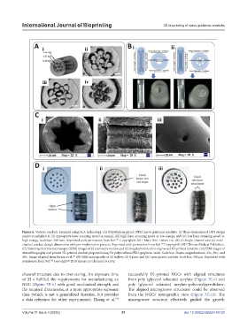
Figure 6. Various conduits prepared using SLA technology. (A) Polyethylene glycol (PEG) nerve guidance conduits. (i) Three-dimensional (3D) design
model crosslinked at (ii) appropriate laser scanning speed or energy, (iii) high laser scanning speed or low energy, and (iv) low laser scanning speed or
high energy. Scale bar: 500 mm. Reprinted with permission from Ref. Copyright© 2011 Mary Ann Liebert Inc. (B) (i) Single-channel and (ii) multi-
142
channel conduit design dimensions with pre-implantation pictures. Reprinted with permission from Ref. Copyright© 2015 Thieme Medical Publishers.
143
(C) Scanning electron microscopic (SEM) images of (i) transverse section and (ii) longitudinal section of grooved 3D-printed conduits. (iii) SEM images of
stereolithography and porous 3D-printed conduit prepared using 5% polyurethane/PEG-graphene oxide. Scale bar: 20 μm, magnifications: 22×, 29×, and
30×. Image adapted from Farzan et al. (D) SEM micrographs of (i) hollow, (ii) 4-pore, and (iii) open pores conduits. Scale bar: 200 μm. Reprinted with
144
permission from Ref. Copyright© 2018 American Chemical Society.
146
channel structure due to over-curing. An exposure time successfully DL-printed NGCs with aligned structures
of 35 s fulfilled the requirements for manufacturing an from poly (glycerol sebacate) acrylate (Figure 7C-i) and
NGC (Figure 7B-ii) with good mechanical strength and poly (glycerol sebacate) acrylate-polyvinylpyrrolidone.
the required dimensions, at a more appropriate exposure The aligned microgroove structures could be observed
time (which is not a generalized duration, but provides from the NGCs’ tomographic view (Figure 7C-iii). The
a data reference for other experiments). Huang et al. microgroove structure effectively guided the growth
156
Volume 11 Issue 4 (2025) 51 doi: 10.36922/IJB025140120