
Page 108 - JCAU-7-3
P. 108
Journal of Chinese
Architecture and Urbanism Seismic performance of reinforced SSPWs
A B
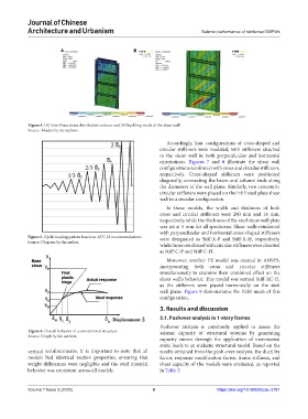
Figure 4. (A) Von Mises stress distribution contour and (B) buckling mode of the shear wall
Source: Models by the authors.
Accordingly, four configurations of cross-shaped and
circular stiffeners were modeled, with stiffeners attached
to the shear wall in both perpendicular and horizontal
orientations. Figures 7 and 8 illustrate the shear wall
configurations reinforced with cross and circular stiffeners,
respectively. Cross-shaped stiffeners were positioned
diagonally, connecting the beam and column ends along
the diameters of the wall plane. Similarly, two concentric
circular stiffeners were placed on the infill steel plate shear
wall in a circular configuration.
In these models, the width and thickness of both
cross and circular stiffeners were 200 mm and 16 mm,
respectively, while the thickness of the steel shear wall plate
was set at 5 mm for all specimens. Shear walls reinforced
with perpendicular and horizontal cross-shaped stiffeners
Figure 5. Cyclic loading pattern based on ATC-24 recommendations were designated as Stiff-X-P and Stiff-X-H, respectively,
Source: Diagram by the author.
while those reinforced with circular stiffeners were denoted
as Stiff-C-P and Stiff-C-H.
Moreover, another FE model was created in ANSYS,
incorporating both cross and circular stiffeners
simultaneously to examine their combined effect on the
shear wall’s behavior. This model was termed Stiff-XC-H,
as the stiffeners were placed horizontally on the steel
wall plane. Figure 9 demonstrates the FEM mesh of this
configuration.
3. Results and discussion
3.1. Pushover analysis in 1-story frames
Pushover analysis is commonly applied to assess the
Figure 6. Overall behavior of a conventional structure seismic capacity of structural systems by generating
Source: Graph by the authors.
capacity curves through the application of incremental
static loads to an inelastic structural model. Based on the
vertical reinforcements. It is important to note that all results obtained from the push-over analysis, the ductility
models had identical section properties, ensuring that factor, response modification factor, frame stiffness, and
weight differences were negligible and the steel material shear capacity of the models were evaluated, as reported
behavior was consistent across all models. in Table 2.
Volume 7 Issue 3 (2025) 6 https://doi.org/10.36922/jcau.5781