
Page 111 - JCAU-7-3
P. 111
Journal of Chinese
Architecture and Urbanism Seismic performance of reinforced SSPWs
stress under load equals or exceeds the yield limit of the 3.4. Effect of the number of stiffeners on frame
same material under simple tension. The equivalent stress performance
( ) is calculated using Equation III:
The effect of the number of stiffeners on the performance
1 of the reinforced frame structure was evaluated using a set
σ − ) +(
1 2 2 2 2 of 3-span, 5-story frames with circular stiffeners arranged
σ
σ
σ = ( 1 σ 2 σ − ) +( σ − ) (III)
e
1
3
2
3
2 in a horizontal configuration. Figure 17 presents the
schematics of the frame model mesh for systems with and
where σ , σ , and σ are the principal stresses. without circular stiffeners.
2
1
3
The ANSYS software calculates the equivalent stress To assess the impact of stiffener quantity, the
using Equation III and presents the output under capacity curves and hysteresis loops of frames with 0,
the abbreviation SEQV. According to this criterion, 2, 3, and 4 circular stiffeners were compared, as shown
it is possible to identify the initiation of failure and in Figures 18 and 19. Initially, pushover analysis was
determine the element from which the failure mechanism conducted for all models, and their capacity diagrams were
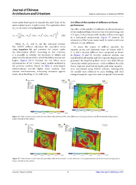
begins. Figures 14-16 illustrate the von Mises stress generated. By simplifying these curves into ideal bilinear
representation of the 1-story frame models analyzed in curves, key seismic parameters – such as stiffness, ductility
the previous sections. Based on Table 2, cross-shaped factor, response modification factor, and shear capacity –
reinforcements provide higher shear capacity than were determined using ANSYS software. Subsequently,
circular reinforcements, enhancing resistance against the models were subjected to cyclic loading, and their
elastic shear buckling of the infill plate. energy absorption capacities were compared. Incremental
A B
Figure 14. Finite element model mesh of a steel shear wall reinforced with cross stiffeners in (A) perpendicular and (B) horizontal configurations
Source: Models by the authors.
A B A
Figure 15. Finite element model mesh of a steel shear wall reinforced with circular stiffeners in (A) perpendicular and (B) horizontal configurations
Source: Models by the authors.
Volume 7 Issue 3 (2025) 9 https://doi.org/10.36922/jcau.5781