
Page 23 - JCTR-10-5
P. 23
Cirrincione | Journal of Clinical and Translational Research 2024; 10(5): 283-290 285
Figure 4. Frontal view with retractor: the interincisive diastema and the
different lengths of teeth 11 and 21 can be observed
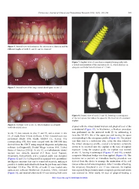
Figure 7. Sagittal view of cone-beam computed tomography with
a virtual representation of the implant in site 12, which displays an
adequate vestibular bone thickness of 1.5 mm
Figure 5. Frontal view of the large mesial-distal space in site 12
Figure 8. Frontal view of teeth 13 and 11, featuring a convergence
of the root apices that reduce the space for the insertion of a standard
implant
Figure 6. Occlusal view in site 12, which displays an adequate
vestibule-palatal space aligned with the virtual dental implant and gingival level of the
contralateral (Figure 15). In Meshmixer, a Boolean procedure
in site 12, two veneers in sites 11 and 21, and a crown in site was performed on the mirrored tooth 22 by subtracting it
22, all made from lithium disilicate. A first intraoral scan was from the 3D STL file of the upper jaw and leaving the space
performed (Medit i500, Medit; MEDIT Co., Korea). The corresponding to the emergence profile (Figure 16). The project
corresponding STL files were merged with the DICOM data was then sent to a technician who, using the data related to
derived from the CBCT using surgical diagnosis and planning the virtual emergency profile, created a temporary composite
software (coDiagnostiX; Dental Wings version 10.8, United crown to be screwed onto the implant at the time of implant
States of America [USA]). At site 12, a small-diameter dental exposure. Using the surgical guide, the implant was inserted
implant was virtually inserted (3.3 Bone Level Tapered; at site 12, leaving it submerged (Figures 17 and 18); a metal-
Straumann, Switzerland), and a surgical guide was designed composite Maryland bridge was then applied (Figure 19). The
(Figures 12 and 13). CoDiagnostiX is equipped with an artificial decision not to perform an immediate loading procedure was
intelligence assistant that can be consulted remotely, making it derived from the desire to manage the maturation of the soft
possible to isolate individual teeth from the jaw bone and obtain tissues at the end of osteointegration. After 3 months of healing,
individual 3D files. The 3D file of tooth 22 was loaded onto the temporary Maryland in site 12 was removed; the implant
open-source software Meshmixer (Autodesk, USA), mirrored was exposed; the previously made composite provisional crown
(Figure 14), and inserted where tooth 12 was missing; both were was screwed in. After nearly 60 days of gingival healing, a
DOI: https://doi.org/10.36922/jctr.24.00035