
Page 36 - MSAM-1-1
P. 36
Materials Science in Additive Manufacturing Cylindrical path planning for AM
3D CAD models of the parts. For the propeller, only one slicing approach. The twist lock pins were printed using
blade is shown as a representative. our developed WAAM system. WAAM is a subcategory
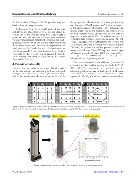
As shown in Figure 3, the CAD model of the twist of the directed energy deposition (DED) technique that
lock pin is first sliced into layers of polygon along the utilizes metal wire as the feedstock and electric arc as
central axis of the cylinder. Once this polygon data is the heat source to build a 3D part layer by layer with the
[17-19]
converted into the universal 3D polar data structure, help of a motion system. The system used for the
various cylindrical print paths for the twist lock pin can be cylindrical print consists of a robot manipulator (ABB IRB
generated, with the linear and circular raster paths being 1660ID) equipped with a welding torch 165 (Fronius WF
the examples shown here. Similarly, for the propeller case 25i Robacta Drive) and a welding power source (Fronius
study, once the CAD model has been sliced and converted TPS 400i) to perform the additive process, as well as a
into the universal 3D polar data structure, the cylindrical rotary table (Sherline 3700-CNC) equipped with a 3-jaw
print path for the propeller can be generated, with the self-centering chuck (Sherline 1040) and powered by a
hybrid contour and zigzag infill path being the example motor (SmartMotor SM23165D) to rotate the cylindrical
illustrated in Figure 4. substrate during the printing process.
The substrate material is the AISI 4340 (condition V)
4. Experimental results cylindrical steel bar and the welding wire is the BOHLER
In this section, we performed the actual cylindrical prints X96 L-MC. The components were printed using the
for the twist lock pin case study using the linear raster path following print parameters: A torch speed of 14 mm/s,
strategy on two different sizes of the cylindrical substrates a wire feed rate of 8 m/min, the gas composition of 90%
and to also demonstrate the ease of adaptability of the argon and 10% CO , and an inter-pass temperature of not
2
A B C
Figure 2. Simple examples of the three different generated paths from the universal data structure: (A) Linear raster path parallel to the cylindrical axial
direction, (B) circular raster path along the cylindrical circumferential direction, and (C) hybrid contour and zigzag path.
Figure 3. Generation of linear and circular raster print paths for the twist lock pin case study.
Volume 1 Issue 1 (2022) 4 https://doi.org/10.18063/msam.v1i1.3