
Page 37 - MSAM-1-1
P. 37
Materials Science in Additive Manufacturing Cylindrical path planning for AM
Figure 4. Generation of hybrid contour and zigzag infill print path for the
propeller case study.
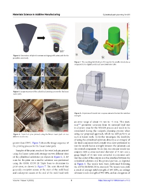
Figure 7. The resulting twist lock pin 3D scan for the smaller stock size as
compared to its digital model and associated error plot.
Figure 5. Image sequence of the cylindrical printing process for the linear
raster path.
Figure 8. Depiction of tensile test coupons extracted to test the interface
strength.
an error range of about +5 mm to −5 mm. This start-
stop geometric variation from its nominal bead size
[20]
is a known issue for the WAAM process and needs to be
considered during the toolpath planning process when
Figure 6. Twist lock pins printed using the linear raster path on two using our proposed approach, which we will perform as
different stocks size. such of future work. To further investigate the feasibility
of using the cylindrical substrate directly as an integral of
greater than 150°C. Figure 5 shows the image sequence of the final component itself, tensile tests were performed to
the printing process for the linear raster path. test the tensile fusion strength between the substrate and
the printed component. To do this, two circular tensile test
Samples of the print results of the twist lock pin printed coupons with a cross-sectional diameter of 4 mm and a
using the linear raster path strategy on two different sizes gauge length of 16 mm were extracted in a manner such
of the cylindrical substrates are shown in Figure 6. A 3D that the center of the coupon is at the interface between the
scan for the print on a smaller substrate was performed cylindrical substrate and the printed portion, as depicted
using the GOM ATOS III Triple Scan to determine its in Figure 8. The tensile tests were performed following
print error, as shown in Figure 7. The scan showed that the ASTM E8/E8M-2016a standard. The tensile tests yield
generally overprint occurs at the start of the weld bead a result of average yield strength of 895 MPa, an average
and underprint occurs at the end of the weld bead with ultimate tensile strength of 991 MPa, and an elongation of
Volume 1 Issue 1 (2022) 5 https://doi.org/10.18063/msam.v1i1.3