
Page 34 - MSAM-1-1
P. 34
Materials Science in Additive Manufacturing Cylindrical path planning for AM
always a limit to the overhang angle that can be printed required for the print. The output of this step is an array of
without support. closed polylines (or polygons) describing the shape of the
When fabricating cylindrical-shaped components, such contours of each sliced layer.
as propellers, a lot of support structures might be needed Next, we want to create a data structure for the
throughout the print due to their curved or revolving coordinate points in the polar coordinate. We create a t ×
nature. As such, there is also an increasing interest in l × m matrix, where t is the total number of sliced layers
performing the material deposition on a cylindrical in the z-axis, l is the total number of discretized polar
surface instead of a planar surface so that each new layer angles θ in the angular axis, and m is the total number of
can be printed on the previous layer without needing a discretized polar distance r in the radial axis. Again, the
lot or even any support structures, as well as to reduce discretization of the polar angle and polar distance can
the discontinuities produced when using planar slicing be based on the required print resolution or accuracy.
for cylindrical-shaped components like propeller. [15,16] The entry to each element in the 3D matrix is an integer
Furthermore, when printing on a cylindrical substrate, the value representing whether the point P(z,θ,r) is inside the
cylindrical feedstock can directly become a portion of the contours of the shape to be printed, with 1 being inside
final component itself, leaving behind the need to cut off and 0 otherwise. This can be done by checking whether
the printed component from the base substrate in the post- the corresponding Cartesian coordinate is inside the
processing step. polygons obtained from the previous step using the point-
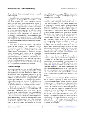
In this paper, we present our approach to performing in-polygon algorithm. Hence, the output of this step is a t
cylindrical path planning through converting a planar × l × m matrix representing points in the polar coordinate
slicing into a universal 3D polar data structure. The whose integer entries signify whether the points are inside
approach is capable of generating cylindrical print the shape to be printed, as exemplified in Figure 1. We then
paths of various patterns so as to reduce the need for have a universal data structure in polar coordinate that is
support structures when printing on a cylindrically useful for subsequent cylindrical planning.
shaped component. We demonstrate the capability of the
approach to planning the cylindrical print paths for two Once we have the universal 3D data structure for the
different revolved components and three different printing discretized points in polar coordinate, we can perform the
patterns. Actual printing experiments and tensile tests of cylindrical path planning. Note that for cylindrical print,
the cylindrical part on the wire arc additive manufacturing the radial axis becomes the build direction instead of the
(WAAM) process were conducted and reported. usual z-axis. Hence, each of the 2D matrices or tables
illustrated in Figure 1 constitutes information for a sliced
2. Methodology layer. From there, we can then decide how we want to plan
the print path for each layer based on the integer state data
In this section, we present our approach to performing
cylindrical slicing and print path planning for general that have been gathered. In the following subsections, we
cylindrical-shaped parts. The method takes in the STL file will describe the techniques to generate the three different
of the 3D CAD model and is capable of generating various print strategies that were mentioned at the start of this
print path strategies depending on the printing needs and section.
suitability, for example, (1) linear raster path parallel to the Common to the three strategies, the data structure can
cylindrical axial direction, (2) circular raster path along the first be simplified depending on radius of the feedstock
cylindrical circumferential direction, (3) hybrid contour (cylindrical substrate) used and the required print layer
and zigzag path, etc. The key to this adaptability is to create height. Initially, the polar points were discretized refined
the universal data structure in a polar coordinate system. to ensure that no information is lost when generating the
The STL file of the 3D CAD model is first sliced using universal 3D polar data. However, the required print layer
off-the-shelf slicing software (e.g., Autodesk Netfabb) and height might be several times larger than the discretization
exported as CLI file format. When slicing the STL file, the resolution. To reduce the 3D polar data, one may extract
3D model of the cylindrical-shaped part is oriented such only the 2D matrix data at the required layer height.
that the central axis of the cylinder is parallel to the vertical For example, assuming that, based on the radius of the
z-axis of the slicer and is positioned at the origin of the feedstock used, the print is to start from layer , and that the
slicer. This is so that it is easier for later process to convert layer height is n times the discretization resolution in the
the Cartesian coordinate points into polar coordinate radial axis (Δr = r −r ), one can just extract and use the
j−1
j
points for the cylindrical path planning purpose. The data for layers r , r , r f+2n , r for the subsequent processing
m
f+n
f
height of the sliced layer is the resolution or accuracy to generate the print path.
Volume 1 Issue 1 (2022) 2 https://doi.org/10.18063/msam.v1i1.3