
Page 35 - MSAM-1-1
P. 35
Materials Science in Additive Manufacturing Cylindrical path planning for AM
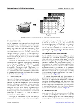
Figure 1. Illustration of the universal data structure for the points in the polar coordinate.
2.1. Linear raster path printing state of the point P(z,θ,r) with z ∈ {z , z , z 1+2s ,
1
1+s
For the linear raster print path parallel to the cylindrical z } θ ∈ [θ , θ] and r ∈ {r , r , r f+2n , r }. From here, by
m
1
f
f+n
t
l
axial direction, the print direction is along the z-axis. connecting the points with the integer state 1 (i.e., material
As such, the hatching or step-over direction is along the to be deposited) along the angular axis for each z and r
(i.e., per row), the circular raster path along the cylindrical
angular axis. Similar to the data simplification in the radial circumferential direction can then be generated, as shown
axis described in the previous paragraph, the 3D polar in the simple example in Figure 2B.
data can be further condensed according to the required
hatching or step-over distance. If the hatching or step- 2.3. Hybrid contour and zigzag infill path
over distance is q times the discretization resolution in the For the hybrid contour and zigzag infill path, further
angular axis (Δθ = θ −θ ), one can just extract the data for processing of the 3D polar data is necessary. The contour
k−1
k
columns θ , θ , θ , θ.
1 1+q 1+2q l points need to first be detected and set apart. This can be
Once these are extracted, the 3D polar data have been done by scanning through the integer state values (either
compressed into columns of integer values representing per column or per row) and assigning a state value of 2 to
the printing state of the point P(z,θ,r) with z ∈ [z , zt], the entry which has a value of 1 and whose neighbors (either
1
θ ∈ {θ , θ , θ , θ} and r ∈ {r , r , r f+2n , r }. From here, the point before or after or both) have a value of 0. This
1 1+q 1+2q
f
l
f+n
m
by connecting the points with the integer state 1 (i.e., integer state value of 2 then indicates that the coordinate
material to be deposited) along the z-axis for each θ and r point is a contour point. Once the contour points have been
(i.e., per column), the linear raster print path parallel to the detected, the contour path can be generated by connecting
cylindrical axial direction can then be generated, as shown the points having the integer state value of 2, as shown in
in the simple example in Figure 2A. the simple example in Figure 2C.
2.2. Circular raster path To generate the zigzag infill path, the procedure to
generate a raster path as described in the previous two
Opposite to the linear raster path, the print direction for the subsections can be performed to first generate a raster infill
circular raster path along the cylindrical circumferential path (either along the cylindrical axial direction or along
direction is along the angular axis, while its hatching the cylindrical circumferential direction). Once the raster
direction is along the z-axis. Similar to the procedure for infill path has been generated, the zigzag infill path can then
the linear raster path, the 3D polar data can be further be generated by connecting these raster lines at alternate
condensed according to the required hatching or step- ends, as shown in the simple example in Figure 2C.
over distance but this time round along the z-axis. If the
hatching or step-over distance is s times the discretization 3. Simulation results
resolution in the z-axis (Δz = z −z ), one can just extract In this section, we show the application of our methodology
h−1
h
the data for rows z , z , z , z .
1 1+s 1+2s t to generate cylindrical print paths for some actual and
Once these are extracted, the 3D polar data have been common cylindrical-shaped spare parts, namely, twist lock
compressed into rows of integer values representing the pin and propeller. For both components, we start with the
Volume 1 Issue 1 (2022) 3 https://doi.org/10.18063/msam.v1i1.3