
Page 38 - MSAM-2-3
P. 38
Materials Science in Additive Manufacturing Cast and 3D-printed fiber orientations
A B
C D
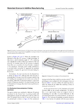
Figure 23. Results of mechanical property: (A) Tensile stress versus tensile strain of specimens through the different casting approaches; (B) flexural stress
versus deflection distance of specimens through different casting methods; (C) schematically shows the load direction of tensile test; and (D) schematically
shows the load direction of flexural test.
shown in Figure 23C and D. When the specimens are
fabricated using the DC process, a high percentage of
fibers have a small inclination angle (0 – 15°), indicating
that a significant number of fibers are oriented in the load
direction. In contrast, when the RC process is adopted,
fewer fibers are oriented in the load direction compared
to DC specimens. Therefore, better tensile performance
is achieved when using the DC approach for specimen
preparation compared to specimens fabricated using the
RC process.
Furthermore, the load direction for the flexural test
is shown in Figure 23D. Although the load direction is Figure 24. Printing path for specimens of the mechanical test.
perpendicular to the specimen, the stress generated during
the bending test acts perpendicular to the cross-section of testing method has been stated in a previous study . The
[31]
specimens. When the DC process is adopted, a significant printing parameters adopted for fabricating specimens are
number of fibers are oriented in the stress direction during listed in Table 3. Test run 1 follows the matching criteria,
the flexural test. Consequently, better flexural performance while the others do not follow the matching criteria, as
is achieved. discussed in Section 3.3.
5.4. Mechanical characterization: Printing As discussed in Section 3.3, the dimensions of printed
specimens filaments differ in the second configuration. To address
The gantry printer was employed to fabricate 3D-printed this, a new experimental setup was designed aimed at
specimens for the flexural test. A printing nozzle with diminishing the size effect of printed filaments on the
approximately 30 mm in length and 15 mm in width was mechanical properties of printed specimens, as shown in
used. The standoff distance was 15 mm for each layer, and Figure 25. For each pair of printing parameters listed in
the printed path is shown in Figure 24. The mechanical Table 3, two batches of materials with the same mixture
Volume 2 Issue 3 (2023) 14 https://doi.org/10.36922/msam.1603