
Page 51 - MSAM-3-4
P. 51
Materials Science in Additive Manufacturing Directed energy deposition
structure in H-DED coatings is expected to improve HV of the B-DED coating. This can be explained by the
0.5
their wear resistance. Hall-Petch relationship. In Figure 5, the H-DED coating,
34
featuring a uniform eutectic structure with a high volume
As featured in Figure 5C and D, the matrix of both
deposition coatings underwent a phase transition from fraction, is less susceptible to severe scratching by hard
ferrite-pearlite to martensitic-cementite. Studies have chips under alternating shear stresses, thereby improving
30
25,28
indicated that the melting of DI during the DED process wear resistance.
always begins with the material surrounding its graphite In addition, the high-temperature molten pool in the
nodules. This is related to graphite’s high laser absorption DED process promotes solid solution strengthening among
rate and heat capacity. During deposition, the melt pool alloy elements. The microstructure of the H-DED coating
31
temperature reaches above the austenitization temperature, displays a higher volume fraction of eutectic skeleton
transforming the ferrite-pearlite matrix to austenite. and significant segregation of hard phase elements, such
During the cooling process, graphite accumulates a large as Cr and C, further enhancing the overall strength of
amount of heat as an uneven heat source, resulting in a the coating. The combination of these factors endows
slow cooling rate around it and a fast cooling rate away the H-DED coating, prepared by the DED process, with
from the graphite. This provides the conditions for the excellent hardness and strength.
directional transformation of austenite into martensite and Figure 9A and B features the 3D and 2D profiles of the
cementite. 30,32 wear tracks on the coating and substrate specimens. The
Elemental segregation occurs due to the different results indicate that the DI specimen has the deepest and
melting points of elements during the initial solidification widest wear track, followed by the B-DED coating, while the
stage, and micro-segregation of elements is a fundamental H-DED coating exhibits the most minor wear. The H-DED
phenomenon that occurs during the solidification of coating demonstrates the highest wear resistance, with a
-3
hypoeutectic alloys. 23,33 Table 2 and Figure 7 indicate that wear rate of 1.575 × 10 mm³/N·m, which is equivalent to
the eutectic structure is rich in hard phase elements, such 31.735% of the wear rate of the DI specimen and 51.586%
as Cr and C, mainly M C carbide, while the dendrite of the wear rate of the B-DED coating (Figure 9C). This
23
6
contains more Fe and Ni, mainly γ-Fe. It has been reported relationship between wear resistance and hardness is
that hard phase elements, such as Cr and C, which are consistent with Archard’s law. 25
enriched in the eutectic structure, can enhance the strength The friction coefficient curves in Figure 9D can be
and toughness of the eutectic skeleton, thereby improving divided into the running-in period and the steady wear
hardness and wear resistance. 25,28 period. The running-in period for the DI specimen and
the H-DED coating is relatively short, about 7 min; the
3.4. Hardness and wear resistance
B-DED coating has a more extended running-in period,
The microhardness of the coatings prepared by different exceeding 10 min. Figure 9E indicates that the average
processes is presented in Figure 8, where the gray area friction coefficients of the DI specimen and the H-DED
distinguishes the thickness of the different coatings. It can coating are similar, around 0.61, while the B-DED coating
be observed that the coatings have higher microhardness has a higher average friction coefficient, reaching 0.709.
than the substrate. The H-DED coating has the highest The trend in wear rate does not correspond with the trend
hardness of 317.66 HV , 19.02% higher than the 266.90 in friction coefficient, mainly because the graphite nodules
0.5
A B
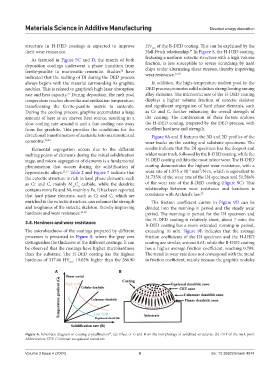
Figure 6. Schematic diagram of coating crystallization . (a) Effect of G and R on the morphology of solidified structures. (b) CET of the melt pool.
28
Abbreviation: CET: Columnar to equiaxial transition
Volume 3 Issue 4 (2024) 6 doi: 10.36922/msam.4974