
Page 48 - MSAM-3-4
P. 48
Materials Science in Additive Manufacturing Directed energy deposition
A B
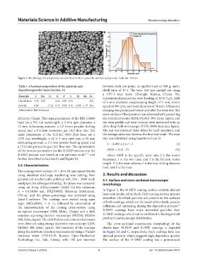
Figure 1. Morphology (A) and particle size distribution (B) of austenitic stainless steel powder. Scale bar: 100 μm
Table 1. Chemical composition of the substrate and between each test point, an applied load of 500 g, and a
deposition powder (mass fraction, %) dwell time of 15 s. The wear test was carried out using
a CFT-I wear tester (Zhongke Kaihua, China). The
Materials C Mn Cr Si P S Ni Mo Fe experimental parameters were: loading of 30 N, Si N balls
4
3
Ductile iron 3.38 0.36 - 2.52 0.03 0.01 - - Bal. of 5 mm diameter, reciprocating length of 5 mm, motor
Powder 0.06 - 17.12 0.75 0.01 0.01 10.86 1.75 Bal. speed of 300 rpm, and wear duration of 30 min. Ultrasonic
Abbreviation: Bal.: Balanced. cleaning was performed before and after the wear test. The
worn surface of the specimen was observed with a scanning
ACunity, China). The main parameters of the RFL-C4000 electron microscope (SEM; SIGMA 300; Zeiss, Japan), and
laser are a 915 nm wavelength, a 3 mm spot diameter, a the wear profile and wear volume were measured with an
12 mm defocusing amount, a 2.2 r/min powder feeding ultra-deep field microscope (VHX-2000; Keyence; Japan).
speed, and a 9 L/min protective gas (Ar) flow rate. The The test was repeated three times for each specimen, and
main parameters of the YLS-KC 6000 fiber laser are a the average value was taken as the final test result. The wear
1070 nm wavelength, a 12 × 3 mm spot size, a 30 mm rate was calculated using Equations I and II:
defocusing amount, a 2 r/min powder feeding speed, and L = 0.002 × f × t × l (I)
a 15 L/min protective gas (Ar) flow rate. The optimization
of the process parameters for the H-DED process and the SWR = V/(L · F) (II)
B-DED process was based on our previous work 23-25 and where SWR is the specific wear rate, f is the motor
further described in Section S1 and Figure S1. frequency, t is the test time, and l is the friction stroke
length. V is the wear volume, L is the total sliding distance
2.3. Characterization
load, and F is the load.
The coatings were cut into 10 × 10 × 10 mm square blocks
using electrical discharge machining wire cutting, then 3. Results and discussion
ground and mechanically polished with 240 – 3000 mesh 3.1. Surface and cross-sectional macroscopic
sandpaper for subsequent testing. The phase was measured morphology
using an X-ray diffractometer (XRD; Cu Kα radiation;
λ = 0.154060 nm; DX2700BH; Haoyuan Instrument, In Figure 2, the H-DED coating surface exhibits distinct
China), and the phase percentage was analyzed using laser scan tracks, while the B-DED coating surface appears
Jade6.5 software. The coatings were etched using aqua smoother. Unmelted particles are present on the surfaces
regia (HCL:HNO = 3: 1), followed by observation of of both coatings, which are the result of inevitable powder
3
25
the microstructure of the coating cross-section using collisions and sputtering during the deposition process.
an optical microscope (OM; Motic, China) and a field B-DED coatings have more unmelted particles than
emission scanning electron microscope (FESEM; SIGMA H-DED coatings, which can be attributed to the larger melt
300; Zeiss, Japan). The distribution and content of elements pool and uneven energy distribution.
were detected using energy dispersive spectroscopy (EDS; The cross-sectional macroscopic morphology of the
SIGMA 300; Zeiss, Japan). The hardness of the coatings double-layer H-DED and B-DED coatings is depicted
along the substrate direction was measured using a Vickers in Figure 3A and C, respectively. Both coatings have low
hardness tester (HMAS-D; Runyan Opto-Mechanical internal porosity, which suggests high deposition quality.
Technology Co., Ltd., China), with 150 μm intervals The surface of the H-DED coating has a pronounced
Volume 3 Issue 4 (2024) 3 doi: 10.36922/msam.4974