
Page 108 - MSAM-4-2
P. 108
Materials Science in Additive Manufacturing Impact of cell angle on AlSi10Mg structures
Table 1. Chemical composition of AlSi10Mg powder
Element Aluminium Silicon Magnesium Iron Copper Manganese Titanium Oxygen
Composition (weight %) Bal 10.20 0.35 0.038 <0.01 <0.01 <0.01 0.045
A B
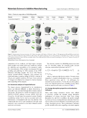
Figure 2. Design process of porous structures. (A) Dodeca structures, with Dodeca-A P80 and Dodeca-A P90 representing 80% and 90% porosity levels,
respectively. Dodeca-B P80 and Dodeca-B P90 are achieved by a 90° rotation around the X-axis, whereas Dodeca-C P80 and Dodeca-C P90 are formed by
a 90° rotation around the Y-axis. (B) Octa structures, where Octa-B P80 and Octa-B P90 are created by rotating the Y-axis by 54.7° and the Z-axis by 45°
from the position of Octa-A
Abbreviations: Dodeca: Dodecahedral; Octa: Octahedral
comparison of low, medium, and high-impact energies. The fracture criterion for AlSi10Mg porous structures
Three samples were tested under each condition to ensure can be described using the Johnson–Cook fracture
the reliability and repeatability of the presented results. criterion, expressed in Equations I and II: 46-48
The microstructure of the samples was prepared through * * * )
( + (D
grinding and polishing for SEM analysis of the LPBF- ε 0 = 1 + D exp 3 σ ) 1 4 ln ε D & p )( + D 1 D T (I)
2
5
fabricated AlSi10Mg samples. The X-CT (GE Vtomex
system, General Electric Company, USA) analysis was σ*=σ /σ Mises (II)
m
performed using a scanning voltage of 130 kV, a current of where ε represents the fracture strain, σ*denotes stress
0
150 μA, and a spatial resolution of 5.5 μm. Cross-sectional triaxiality, σ stands for hydrostatic stress, σ represents
m
Mises
CT images were obtained to evaluate the internal structure Mises equivalent stress, and D – D encompass the
5
1
and morphology of the samples. material model parameters, έ is the dimensionless plastic
∗
strain rate. Relevant parameters, including density, elastic
2.4. Numerical analysis of impact behavior modulus, and Poisson’s ratio, are shown in Table 3.
The impact process, characterized by its instantaneous
nature and inherent difficulty in direct observation, is 2.5. Energy absorption properties and evaluation
more effectively examined through finite element analysis indicators
simulations. The geometric model was imported into the Three main energy absorption metrics were utilized
ANSYS/LS-DYNA software (version ANSYS 2023 R1) to effectively evaluate the dynamic energy absorption
(Ansys Inc., United States) for numerical analysis. Notably, performance of porous structures: Peak force, energy
considering various factors such as accuracy and cost- absorption (E ), and SEA. In addition, the specific strength
a
effectiveness, a tetrahedral mesh type was selected, with (S ) index serves as a crucial performance indicator. Peak force
p
a final mesh size of 0.25 mm determined through mesh represents the maximum initial force exerted during the entire
sensitivity tests conducted on the finite element model’s energy absorption process. These performance indicators
mesh size and density. provide valuable information regarding a structure’s capacity
Volume 4 Issue 2 (2025) 4 doi: 10.36922/MSAM025130019