
Page 107 - MSAM-4-2
P. 107
Materials Science in Additive Manufacturing Impact of cell angle on AlSi10Mg structures
the effects of unit cell orientation and porosity level on high-purity argon gas is introduced into the chamber to
impact resistance and energy absorption. minimize oxidation (oxygen levels below 1,000 ppm) and
In this study, Dodeca and Octa porous structures with ensure a stable processing environment.
varying rotation angles were designed and fabricated 2.2. Design of porous structures
using AlSi10Mg through LPBF technology. Scanning
electron microscopy (SEM) and X-ray computed The implementation of an organized Voronoi structure
tomography (X-CT) were utilized to characterize the design method utilizing Rhinoceros 5 (McNeel,
effects of LPBF process parameters on microstructure, United States), along with its Grasshopper plugin
defects, and dimensional resolution. The research (version 0.9.0076), was employed to create Dodeca
focuses on the experimental investigation of the and Octa structures. In Figure 2A, Dodeca-A P80 and
mechanical behavior of these porous metallic structures Dodeca-A P90 designations correspond to 80% and 90%
under dynamic loading conditions, supplemented by porosity levels, respectively. The cell geometry of Dodeca-B
finite element analysis simulations. The deformation P80 and Dodeca-B P90 is achieved by rotating the single-
mechanisms were systematically examined, and the unit cell 90° around the X-axis based on the position of
energy absorption properties of the structures were Dodeca-A. In contrast, the geometry of Dodeca-C P80
evaluated, emphasizing the significant influence of and Dodeca-C P90 is formed by a 90° rotation around the
single-unit cell rotation on their performance. The Y-axis (Figure 2A). As shown in Figure 2B, the Octa-B P80
ultimate aim is to provide theoretical insights to enhance and Octa-B P90 structures are created by first rotating the
the optimization and practical application of porous Y-axis by 54.7° and then rotating the Z-axis by 45° of the
structures in engineering. single-unit cell relative to the position of Octa-A. These
specific rotations are designed to optimize and compare
2. Materials and methods mechanical performance and energy absorption by altering
2.1. Materials and manufacturing the alignment of the unit cells. The overall dimensions of
all the samples are 30 × 30 × 30 mm . To maintain the load-
3
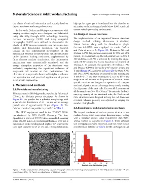
This study used AlSi10Mg powder, supplied by Falcontech carrying capacity of the structural rods, the Dodeca and
(China), to fabricate porous structures. As shown in Octa structures were designed to keep the rod diameters
Figure 1A, the powder has a spherical morphology with constant, whereas porosity was adjusted by varying the
a particle size distribution of 10 – 55 μm and an average number of single cells.
particle size of approximately 25 μm (Figure 1B). The
detailed chemical composition is provided in Table 1. 2.3. Experimental and characterization methods
The LPBF equipment used is the EOSINT M280, The impact resistance of various porous structures was
manufactured by EOS GmbH, Germany. The laser evaluated using room temperature hammer impact testing
operates at a power of 370 W, with a controlled scanning with a hammer impact tester (CEAS9350, INSTRON,
speed of 1,335 mm/s. A powder layer thickness of 30 μm is United States), as depicted in Figure 3. Three different
maintained, with a rotating hatch angle of 67°, whereas the test configurations were employed, and the experimental
laser spot diameter is set at 170 μm. During fabrication, conditions are detailed in Table 2 for the investigation and
A B
Figure 1. Powder characteristics. (A) Scanning electron micrograph shows the morphological characteristics of AlSi10Mg powder. Scale bar: 100 μm,
magnification: 130×. (B) Particle size distribution of AlSi10Mg powder
Volume 4 Issue 2 (2025) 3 doi: 10.36922/MSAM025130019