
Page 33 - MSAM-4-2
P. 33
Materials Science in Additive Manufacturing Measuring the porosity of AM components
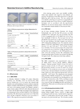
A B C After printing, green parts were initially available,
which were analyzed with regard to their density and
porosity. The green parts were then subjected to a catalytic
debinding and sintering process. This was carried out
externally by a sintering service provider recognized by the
material manufacturer (Elnik System GmbH, Waldachtal,
Germany) and in accordance with the specifications
Figure 4. Computer-aided designs of the test components: (A) Cuboid, defined by the material manufacturer. After this process,
34
(B) cylinder, and (C) femoral ball head the components consist entirely of 316L stainless steel.
Table 4. FDM process parameters and part dimensions for 3.1.2. PBF (SLS)
printing. An S2 laser sintering system (Sintratec AG, Brugg,
Parameter Cuboid Cylinder Femoral ball head Switzerland) was used for the SLS process, in which
Extruder temperature (°C) 235 powdered PA12 (Sintratec AG) was processed. The SLS
Print speed (mm/s) 10 printer is equipped with a 10 W diode laser, which has a
laser wavelength of 1064 nm. The laser spot size was 145
Infill density (%) 100 μm and the scan speed 3 m/s. A value of 0.1 mm was preset
Heater chamber 80 for the layer thickness. The build chamber was heated to
temperature (°C) 180°C during the printing process. The apparent powder
Layer height (mm) 0.14 density of the PA12, determined using a gas pycnometer
Support Raft Raft Brim (Section 3.2), was 1.065 g/cm³. The Sintratec Central2
Part dimensions (mm) 15×15×20 Ø15×20 Ø32 slicer (Sintratec AG) was used to prepare the components.
All components were printed in a single printing process
and had the same dimensions as the FDM-printed green
Table 5. LCM process parameters and part dimensions for
printing parts. After the printing process, the components were
cleaned and the residual powder was removed by blasting
Parameter Cuboid Cylinder Femoral ball head with glass beads. The components were then analyzed.
DLP energy (mJ/cm²) 100
DLP intensity (mW/cm²) 73.8 3.1.3. PBF (EBM)
Setting time (s) 4 The EBM components were manufactured using an
Tilting speed (°/s) 15 A1 EBM system (Arcam SE/GE Additive, Mölndal,
Layer height (mm) 0.025 Sweden). Titanium powder Ti6Al4V (Arcam SE) with an
apparent powder density of 4.433 g/cm³ determined by
Support ‑ ‑ Raft gas pycnometry (Section 3.2) was also used. The process
Part dimensions (mm) 10×10×10 Ø10×10 Ø16 parameters of the production process were set internally
Abbreviation: DLP: Digital light processing. on the system. The layer thickness was 0.05 mm, maximum
beam current 39.5 mA, hatch spacing 0.05 mm, and scan
3.1. AM processes speed 800 – 11279 mm/s. The components were prepared
using Autodesk Netfabb (Autodesk Inc., San Rafael, USA).
3.1.1. MEX (FDM) All components were printed in one printing process and
A Makerbot Method X desktop 3D printer (MakerBot had the same dimensions as the FDM-printed green parts
Industries LLC, Brooklyn, USA) was used for the FDM and the SLS components. After printing, the components
process. Furthermore, a 0.4 mm nozzle and a heated build were removed from the building platform and cleaned by
chamber were used for printing. The metal-polymer composite sandblasting. These post-processing steps were followed by
filament Ultrafuse 316l (BASF SE, Ludwigshafen, Germany) the analyses.
was used as the printing material. The filament contains a
metal powder content of 80 wt% with a filament diameter of 3.1.4. VAT photopolymerization (LCM)
1.75 mm. The STL files of the part designs were prepared for LCM components were printed using a CeraFab 7500
printing using the slicer software Makerbot Print (MakerBot system (Lithoz GmbH, Vienna, Austria). A digital light
Industries). The relevant process parameters set in MakerBot processing principle was used. A photoreactive suspension
Print and the component dimensions are summarized in (slurry) of methacrylates and zirconium powder (Lithoz)
Table 4. All components were printed individually. was used as the print material type. The zirconium powder
Volume 4 Issue 2 (2025) 7 doi: 10.36922/MSAM025090010