
Page 36 - MSAM-4-2
P. 36
Materials Science in Additive Manufacturing Measuring the porosity of AM components
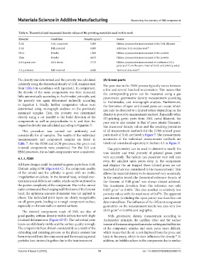
Table 6. Theoretical and measured density values of the printing materials used in this work
Material Condition Density (g/cm ) Source
3
316L 316L composite 5.000 Helium pycnometer measurement of the 316L filament
316L Full material 8.000 AISI type 316L stainless steel 24
PA12 Powder 1.065 Helium pycnometer measurement of the powder
Titan Powder 4.433 Helium pycnometer measurement of the powder
ZrO2 green part ZrO2 slurry 3.715 Helium pycnometer measurement of a reference ZrO2
green part from the same material batch and printing setup
ZrO2 sintered Full material 6.088 Technical data sheet 36
The density was determined and the porosity was calculated (A) Green parts
indirectly using the theoretical density of 316L stainless steel The pore size in the FDM process typically varies between
from Table 6 in accordance with Equation I. In comparison, a few and several hundred micrometers. This means that
the density of the same components was then measured the corresponding pores can be measured using a gas
fully automatically according to Archimedes’ principle, and pycnometer, gravimetric density measurement according
the porosity was again determined indirectly according to Archimedes, and micrograph analysis. Furthermore,
to Equation I. Finally, further comparative values were the formation of open and closed pores can occur, which
determined using micrograph analyses on the previously can only be detected to a limited extent depending on the
examined samples. Here, the porosity was determined density or porosity measurement method. Especially when
directly using a cut parallel to the build direction of the 3D-printing green parts from 316L metal filament, the
components as well as perpendicular to it, and then the pore size is also similar to that of pure plastic filaments.
respective density was calculated according to Equation II. The measured density values and the resulting porosities
This procedure was carried out uniformly and of all measurement methods for the FDM-printed green
consistently for all samples. The results of the individual parts made of 316L are listed in Figure 7. The measurement
measurements and component samples are listed in accuracies of the individual measurement methods are
Table 7. For the FDM and LCM processes, the green and listed and considered separately in Section 4.2 in Figure 8.
sintered components were examined. For the SLS and Gas pycnometry can be used to determine nearly the
EBM processes, the as-built components were considered. true density and total porosity of printed green parts
4.1.1. FDM very accurately. The helium can penetrate very well into
even the smallest open pores deep in the component
All three designs could be printed as green parts from 316L and displace the air trapped there (closed pores are not
filament using FDM (Figure 6A-C). The component quality reached and are not considered in the measurement). This
of the cuboid and the cylinder is good, with no visible allows the material density to be measured very accurately.
irregularities or defects. In the femoral head, isolated over- In the samples tested, the theoretical reference density of
extrusions and defects are visible, which can be attributed to the filament of 5.00 g/cm³ was always almost achieved.
the greater complexity of the component. Due to the curved The maximum deviation from this reference was only
outer contour and the changing wall thickness of the femoral 0.023 g/cm³ or 0.46%. This also resulted in relatively low
head, the optimum amount of material was not applied in porosity values with the maximum of 0.47%. The apparent
places. The individual print layers are clearly recognizable part density (including the open pores) was therefore not
on all green parts, leading to a rough component surface, determined here. The influence of the different component
especially on the side walls or curved surfaces. geometries on the measurement results was also very low
The sintered components made of 316L are also of (0.03 g/cm³ or 0.60%) and negligible.
good quality, without directly visible defects but with slight With gravimetric density measurement according to
localized deformations (Figure 6D-F). The individual print Archimedes’ principle, the capillary effect and the surface
layers are still clearly visible and the surface quality is rough. tension of the measuring medium make wetting and infiltration
The components have shrunk considerably as a result of the of the component samples and open pores more difficult,
debinding and sintering process, as the plastic content has which means that the air is not displaced from the pores and
37
been removed from the component and the remaining metal leads to buoyancy, which in turn influences the density. In
particles have sintered together due to the heat treatment. addition, air bubbles adhere to the components due to surface
Volume 4 Issue 2 (2025) 10 doi: 10.36922/MSAM025090010