
Page 94 - ARNM-2-3
P. 94
Advances in Radiotherapy
& Nuclear Medicine Radiotherapy with neutron/gamma tubes
demonstrated that operating the d-d neutron generator
in continuous wave (CW), with a beam power of 100 kV
and 10 mA, can generate a neutron yield of 3.3 × 10 n/s
9
with a neutron flux ~ 8 × 10 n/cm /s at the center of the
7
2
irradiation window. The delivered dose rate is about 2 Gray
(RBE)/min, resulting in 4 – 9 min of treatment time. The
3
new mini d-d neutron tube can provide high peak neutron
doses in pulsed mode operation. By operating the mini
neutron tube at 500 kV and 10 mA of D ion beam current,
−
the peak neutron yield is 5 × 10 n/s. The average neutron
10
yield becomes 5 × 10 n/s for a 10% DF (1 ms, 100 Hz)
9
operation. Thus, the treatment time should be about the
same as the larger D ion-based d-d neutron generator. By
+
positioning the beam target near the center of the tumor
bed, one can further increase the neutron flux on the cavity
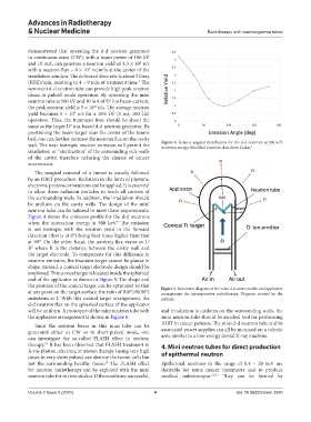
wall. The near isotropic neutron emission will permit the Figure 4. Relative angular distribution for the d-d neutrons at 500 keV
deuteron energy. Modified based on data from Csikai.
9
irradiation or “sterilization” of the surrounding side walls
of the cavity, therefore reducing the chance of cancer
recurrences.
The surgical removal of a tumor is usually followed
by an IORT procedure. Radiation in the form of photons,
electrons, protons, or neutrons can be applied. It is essential
to allow these radiation particles to reach all corners of
the surrounding walls. In addition, the irradiation should
be uniform on the cavity walls. The design of the mini
neutron tube can be tailored to meet these requirements.
Figure 4 shows the emission profile for the d-d neutrons
when the interaction energy is 500 keV. The emission
9
is not isotropic with the neutron yield in the forward
direction (that is at 0°) being four times higher than that
at 90°. On the other hand, the neutron flux varies as 1/
R where R is the distance between the cavity wall and
2
the target electrode. To compensate for this difference in
neutron emission, the titanium target cannot be planar in
shape. Instead, a conical target electrode design should be
employed. This conical target is located inside the spherical
end of the applicator as shown in Figure 5. The shape and
the position of the conical target can be optimized so that Figure 5. Schematic diagram of the mini d-d neutron tube and applicator
at any point on the target surface, the ratio of R(0°)/R(90°) arrangement for intraoperative radiotherapy. Diagram created by the
maintains at 2. With this conical target arrangement, the authors.
d-d neutron flux on the spherical surface of the applicator
will be uniform. A prototype of the mini neutron tube with and irradiation is uniform on the surrounding walls, the
the applicator arrangement is shown in Figure 6. mini neutron tube should be an ideal tool for performing
Since the neutron beam in this mini tube can be IORT in cancer patients. The mini d-d neutron tube and its
generated either in CW or in short-pulsed mode, one associated power supplies can all be mounted on a robotic
can investigate the so-called FLASH effect in neutron arm, similar to a low-energy dental X-ray machine.
therapy. It has been observed that FLASH treatment in 4. Mini neutron tubes for direct production
10
X-ray photon, electron, or proton therapy (using very high of epithermal neutron
doses in very short pulses) can destroy the tumor cells but
not the surrounding healthy tissue. The FLASH effect Epithermal neutrons in the range of 0.4 – 20 keV are
10
for neutron radiotherapy can be explored with the mini desirable for some cancer treatments and to produce
neutron tube for in vitro studies. If the results are successful, medical radioisotopes. 6,7,11 They can be formed by
Volume 2 Issue 3 (2024) 4 doi: 10.36922/arnm.3920