
Page 25 - BH-2-4
P. 25
Brain & Heart Step by step 3D ICE guided LAA occlusion
A B C
Figure 3. ICE views from RV. (A) Anterior tilt until only the lower portion of the tricuspid valve is visible and slow advancement to enter RV. Upon
reaching RV, all tilt is released to rest the probe in the RVOT. (B) LV long axis views to check for pericardial effusion. (C) Q-tip view of the left atrial
appendage to rule out thrombi.
Abbreviations: MV: Mitral valve; LV: Left ventricle; LSPV: Left superior pulmonary vein; LAA: Left atrial appendage; RV: Right ventricle, RVOT: Right
ventricular outflow tract; ICE: Intracardiac echocardiography.
A B C
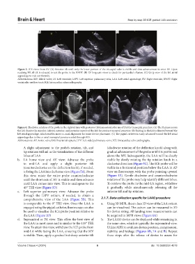
Figure 4. Clockwise rotation of the probe in the right atrium with posterior tilt demonstrates the use of IAS for transeptal puncture. (A) The X-plane across
the IAS depicts the superior, inferior, anterior, and posterior aspects of the IAS for precise transeptal puncture. (B) Tenting in the IAS is directed toward the
left atrial appendage, which enables more co-axial alignment for easier device placement. (C) The pigtail catheter is easily advanced toward the left atrial
appendage due to the co-axial transeptal puncture aided through ICE.
Abbreviations: AV: Aortic valve; IAS: Interatrial septum; LPV: Left-sided pulmonary veins; ICE: Intracardiac echocardiography.
A slight adjustment to the probe’s rotation, tilt, and (clockwise rotation of the deflection knob) along with
tip rotation will aid in the visualization of the different gradual advancement of the probe until it is positioned
lobes of LAA above the MV. Subsequently, the LAA will be clearly
b. LA home view and AV view: Advance the probe visible by slowly rotating the tip rotation knob in a
to mid-LA and apply a slight posterior tilt clockwise direction (Figure 5C). The ICE probe will be
(counterclockwise on the deflection knob), if needed, visible in a horizontal position below the LAA in AP
to bring the LAA into the home view (Figure 5A). From view on fluoroscopy, with the probe pointing upward
this view, rotate the entire probe counterclockwise (Figure 1E). Gentle clockwise and counterclockwise
until the short axis of AV is visible and then advance rotation of the probe may help identify different lobes.
until LAA comes into view. This is analogous to the To retrieve the probe in the mid-LA region, withdraw
45° TEE view (Figure 5D) it gradually while simultaneously releasing all the
c. Left superior pulmonary view: Advance the probe anterior tilt and tip rotation.
through the LSPV ostium, if needed, to obtain a
comprehensive view of the LAA (Figure 5B). This 2.1.7. Data collection specific for LAAO procedure
is comparable to the 0° TEE view. Once the LAA is a. Using 3D MPR, the en-face 3D view of the LAA ostium
engaged using the pigtail catheter, fluoroscopy can also can be visualized. The ostium can be measured in 3D
be used to visualize the ICE probe position relative to for device sizing. All landing zone measurements can
the LAA (Figure 1D) be acquired in MPR views (Figure 6A)
d. Supramitral or PA view: This offers the best view of b. The LAAO device can be deployed while remaining in
the LAA in most cases and is similar to the 135° TEE the same view, which is typically the supramitral view.
view. To attain this view, withdraw the ICE probe from Utilize MPR to evaluate device position, compression,
mid-LA while facing the LAA, ensuring that the MV stability, and leakage (Figures 6B, 7A and B). Repeat
is visible. Then, apply a gradual but sharp anterior tilt these steps after the release of device to assess for
Volume 2 Issue 4 (2024) 6 doi: 10.36922/bh.4018