
Page 86 - DP-2-2
P. 86
Design+ Closed-form solution for pressurized obround shells
simplified to an equivalent circular one. This allows the As an obround shape consists of straight and circular
use of a circular member design process for non-circular sections, finding a stress function that satisfies both
members. straight and circular boundaries is extremely difficult, if not
The American Society of Mechanical Engineers (s) code impossible. Therefore, it is more practical to use separate
adopted this concept by proposing a design-by-role method. stress functions to satisfy different boundary conditions.
In this approach, stresses at three potentially high-stress In this study, the obround shape is divided into curved
locations are estimated using empirical formulas and pre- and straight segments, each with relatively simple geometry
estimated shell thicknesses. The maximum stress obtained and load boundary conditions.
needs to be compared with the allowable stress to confirm For a straight or circular segment with simple
whether the pre-estimated thickness is acceptable. If the boundary loads, theoretical solutions are available.
estimated thickness is found to be inappropriate, adjustments By using the superposition principle, introducing
must be done. The maximum stresses are then recalculated reasonable assumptions, and combining existing closed-
and compared until an acceptable thickness is obtained. 1,2
form solutions of elastic theory, a closed-form solution
Even if the shell thickness is deemed acceptable, the for obround components under internal pressure is
true stress within the shell remains unknown due to the developed. This solution can be used to calculate stresses
inaccuracy of empirical formulas. As a result, the thickness and displacements at locations of interest.
obtained through this process is not necessarily the
minimum required. While this approach is generally safe, Considering the uniqueness of the elastic solution,
it may become overly conservative as the length-to-width this formulation represents the closed-form theoretical
ratio of the obround increases. 3 solution for pressurized obround shells.
At present, there is no empirical formula in design Because the stresses calculated using the proposed
codes for estimating the displacement of obround shells. method are accurate, it is possible to determine the
12
The deformation of obround components is typically minimum required thickness. In addition, this method
determined using numerical analysis methods. can be applied to out-of-roundness analysis. 13
Zheng carried out a theoretical analysis of non-circular 2. Theoretic analysis
4
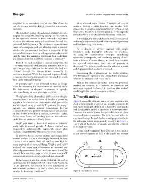
cross-sections. The explicit form of the elastic governing Figure 1 shows the obround shape or cross-section of the
equations for non-circular cross-section shell geometries shell, which consists of curved and straight segments. In
was developed using general shell equations, the energy
method, and various integral formulations. For an this study, the length of the shell is limited to unit length,
elliptical shell whose geometry is relatively simple and can and the analytical model is limited to a plane stress state.
be described by a continuous function, expressions of shell However, the results should be applicable to both plane
forces, shear forces, and bending moments were derived stress and plane strain states. The term “section” refers to
under internal pressure and body forces. a section through the wall thickness and perpendicular to
the thickness, that is, sections A, B, C, and D in Figure 1.
Singh performed a theoretical analysis of obround The origin of the global rectangular coordinates is placed
5
shells with reinforced gussets. A design method was at the section center.
proposed to determine the appropriate gusset plate
locations to reinforce the pressurized obround shells. Letters a and b represent the inside and outside radius
of the curved segment or half of the inside and outside
To improve the accuracy of analysis and design, finite
element analysis (FEA) is increasingly employed for non-
circular pressure vessels. Shah and Pradhan used FEA for
6
stress analysis of an obround flange. Utagikar and Naik
7,8
analyzed the stress and deformation in obround and
elliptical pressure vessels. Pany conducted a non-linear FEA
9
to study the stress states in open-ended pressure vessels with
various cross-sections (circular, elliptical, and obround).
In the present study, the theory of elasticity is used to
derive a closed-form solution for obround shells. According
to this approach, the solution to a two-dimensional or
axisymmetric problem is to find a stress function that
satisfies the boundary conditions. 10 Figure 1. Obround cross-section
Volume 2 Issue 2 (2025) 2 doi: 10.36922/DP025060010