
Page 87 - DP-2-2
P. 87
Design+ Closed-form solution for pressurized obround shells
dimensions. The wall thickness, b-a, is uniform along the other free to move. The load conditions included forces
cross-section. L denotes the half-length of the straight and moments acting at the free end, as well as pressure
segment, and pressure p is applied to the inner surface. acting on the inner surface (left of Figure 3).
Sections A and B mark the junctions between the The straight segment AB can be treated as a simple
curved and straight segments. Sections C and D lie on the support beam, with a potential rigid body motion v in the
0
planes of symmetry, that is, Y=0 and X=0, respectively. vertical direction at the supports, which is induced by the
Considering the symmetry conditions, the analysis curved segment. Due to the symmetric condition, the load
model selected is shown in Figure 2. All internal forces values at both ends of the beam are identical, i.e., F =F ,
By
Ay
and moments at sections A and C were treated as external M =M (right of Figure 3).
A
B
loads, which acted as load boundaries. Section B is the common section or junction between
As section C lies along a plane of symmetry, no shear the curved segment BC and the straight segment AB.
force exists in this section. The total number of unknown All mechanical variables in this section, such as stress,
loads to be determined at the boundaries was five strain, and displacement, should ideally be continuous at
(Figure 2). section B.
Because the forces and bending moments act over unit However, as section B is defined as a load boundary
lengths, their units are N/m and N-m/m, respectively. rather than a displacement boundary, it is impossible
to ensure the complete continuity of all variables. As an
Based on force equilibrium conditions, four equations approximation, only the displacement and rotation angle
can be formulated among the five unknown loads. at the section center are required to be continuous.
F =pa (I) In this study, the rotation angle of a section is defined as
x
F =p(a+L) (II) the rotation angle of a small element located at the center
y
F =PL (III) of the section and along thickness. Clockwise rotation is
considered the positive rotation angle (Figure 4).
Ay
M =M −pL(a+b)/2 (IV) 2.1. Rotation angle of section B
C
A
The load directions are shown in Figure 2.
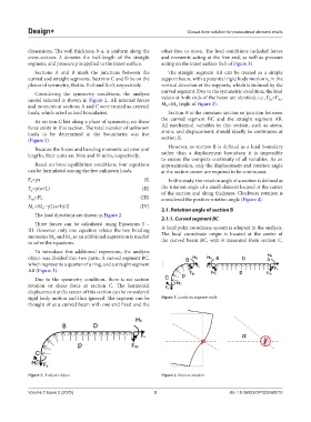
2.1.1. Curved segment BC
Three forces can be calculated using Equations I –
III. However, only one equation relates the two bending A local polar coordinate system is adopted in the analysis.
moments M and M so an additional expression is needed The local coordinate origin is located at the center of
A
C
to solve the equations. the curved beam BC, with θ measured from section C.
To introduce this additional expression, the analysis
object was divided into two parts: A curved segment BC,
which represents a quarter of a ring, and a straight segment
AB (Figure 3).
Due to the symmetry condition, there is no section
rotation or shear force at section C. The horizontal
displacement at the center of this section can be considered
rigid body motion and thus ignored. The segment can be Figure 3. Loads on segment ends
thought of as a curved beam with one end fixed and the
Figure 2. Analysis object Figure 4. Section rotation
Volume 2 Issue 2 (2025) 3 doi: 10.36922/DP025060010