
Page 85 - IJB-1-1
P. 85
Libiao Liu and Xiaohong Wang
thetic biodegraded PU, was firstly built in our group
based on the simulation principles of the hepatic lobe
structure. This structure was printed according to a
CAD model using a one nozzle LDM technology. As
shown in Figure 3, the outer layer of the structure is
an ellipsoidal protective shell. The internal room is
isolated into multiple independent branch channels by
a series of division plates. The branching channels are
arranged around a central axis uniformly and can
transport nutrients to each part of the structure.
Through the branched channels, the surface area/ vo-
lume ratio is greatly expanded. This is beneficial for
the exchange of gas and nutrients inside the con-
struct [56] .
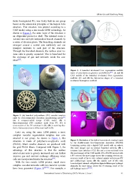
Figure 4. A branched tri-channel liver regeneration scaffold
made of poly (lactic-co-glycolic acid) (PLGA) [63] : (A and B)
CAD models of the branched tri-channel liver regeneration
scaffold; (C) and (D) the fabrication stages of a branched
tri-channel hemisphere scaffold.
Figure 3. (A) branched polyurethane (PU) vascular template
[56]
made by a low-temperature deposition manufacturing system .
(A) A computer-aided design (CAD) model. (B) A
three-dimensional (3D) construct made from PU. (C) A
cross-section of the PU construct in (B). (D) A scanning elec-
tronic microscope picture of the outer wall in (B).
Later on, using the same LDM printer, a more
complex vascular regeneration template was con-
structed in our group. As shown in Figure 4, this
structure is made of poly(lactic-co-glycolic acid) Figure 5. Illustration of the hybrid hierarchical construct made
(PLGA). Much smaller channels are produced with by the double-nozzle low-temperature deposition (DLDM)
bioprinting system: (A) a digital CAD model with an outlook
the grid PLGA fibers. Compared with Figure 3, the (the inset image) and an internal branched network; (B) a
advantage of this structure is that the surface common layer interface (CLI) file and a cross-sectional view
area/volume ratio is greatly increased and can further (the inset image) of the CAD model; (C) a DLDM product with
improve gas and nutrient exchange efficiency when a PU outcoat; the inset image shows the scanning electron mi-
cells are incorporated inside the structure [63] . croscope result of the in vitro cultured sample with porous PU
With the two nozzle LDM printer, much more and cell/hydrogel layers; (D) the middle part of (C) with
branched/grid internal cell/gelatin/alginate/fibrinogen hydrogel
complex vascular networks with two material systems channels; the inset image shows the PI staining result of the
have been generated (Figure 5) [60–62] . For example, a cell/hydrogel section [60–63] .
International Journal of Bioprinting (2015)–Volume 1, Issue 1 81