
Page 267 - IJB-10-1
P. 267
International Journal of Bioprinting Permeability of NiTi gyroid scaffolds
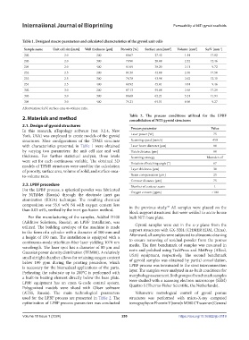
Table 1. Designed macro parameters and calculated characteristics of the gyroid unit cells
Sample name Unit cell size [mm] Wall thickness [μm] Porosity [%] Surface area [mm ] Volume [mm ] Sa/V [mm ]
3
2
-1
202 2.0 200 80.67 27.42 1.54 17.82
203 2.0 300 70.90 28.88 2.32 12.46
204 2.0 400 61.09 30.20 3.11 9.72
252 2.5 200 84.56 42.08 2.40 17.50
253 2.5 300 76.78 43.98 3.62 12.15
254 2.5 400 68.92 45.81 4.84 9.46
302 3.0 200 87.13 59.88 3.46 17.29
303 3.0 300 80.68 62.21 5.21 11.94
304 3.0 400 74.21 64.51 6.96 9.27
Abbreviation: Sa/V, surface-area-to-volume ratio.
2. Materials and method Table 2. The process conditions utilized for the LPBF
consolidation of NiTi gyroid structures
2.1. Design of gyroid structures Process parameter Value
In this research, nTopology software (ver. 3.2.4, New
York, USA) was employed to create models of the gyroid Laser power [W] 75
structures. Nine configurations of the TPMS structure Scanning speed [mm/s] 450
with characteristics presented in Table 1 were obtained Laser beam diameter [μm] 80
by varying two parameters: the unit cell size and wall Hatch distance [μm] 80
thickness. For further statistical analysis, three levels Scanning strategy Meander-off
were set for each continuous variable. The obtained 3D Rotation of hatching angle [°] 67
models of TPMS structures were used for the calculation
of porosity, surface area, volume of solid, and surface-area- Layer thickness [μm] 30
to-volume ratio. Beam compensation [μm] 25
Contour distance [μm] 75
2.2. LPBF procedure Number of contour scans 1
For the LPBF process, a spherical powder was fabricated Oxygen content [ppm] <100
by NiTiMet (Russia) through the electrode inert gas
atomization (EIGA) technique. The resulting chemical
composition was 55.6 wt% Ni with oxygen content less in the previous study. All samples were placed on the
38
than 0.03 wt%, verified by the inert gas fusion method.
block support structures that were welded to an in-house
For the manufacturing of the samples, AddSol D100 built NiTi base plate.
(Additive Solutions, Russia), an LPBF installation, was Gyroid samples were cut in the x–y plane from the
utilized. The building envelope of the machine is made support structures with GX-320L (CHMER EDM, China).
in the form of a cylinder with a diameter of 100 mm and Afterward, all samples were subjected to ultrasonic cleaning
a height of 150 mm. The installation is equipped with a to ensure removing of residual powder from the porous
continuous-mode ytterbium fiber laser yielding 1070 nm media. The first benchmark of samples was mounted in
wavelength. The laser spot has a diameter of 80 μm and resin and polished using TechPress and MetPrep (Allied,
Gaussian power density distribution (TEM00). A relatively USA) equipment, respectively. The second benchmark
small airtight chamber allows for retaining oxygen content of gyroid samples was obtained by partial consolidation,
below 100 ppm during the printing procedure, which LPBF process was terminated in the strut interconnection
is necessary for the biomedical applications of the parts. layer. The samples were analyzed in as-built conditions for
Preheating the substrate up to 200°C is performed with morphology assessment. Both groups of benchmark samples
a built-in heating element directly below the base plate. were studied with a scanning electron microscope (SEM)
LPBF equipment has an open G-code control system. Quattro S (Thermo Fisher Scientific, the Netherlands).
Polygonized models were sliced with Gliser software
(ATSS, Russia). The main technological parameters Volumetric metrological control of gyroid porous
used for the LPBF process are presented in Table 2. The structures was performed with micro-X-ray computed
optimization of LPBF process parameters was conducted tomography on Phoenix V|tome|x M300 CT scanner (General
Volume 10 Issue 1 (2024) 259 https://doi.org/10.36922/ijb.0119