
Page 269 - IJB-10-1
P. 269
International Journal of Bioprinting Permeability of NiTi gyroid scaffolds
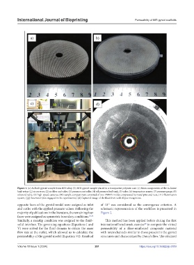
Figure 1. (a) As-built gyroid sample from NiTi alloy. (b) NiTi gyroid sample placed in a transparent polymer case. (c) Main components of the in-house
built setup: (1) air receiver, (2) air filter and valve, (3) pressure controller, (4) oil pressure feed tank, (5) valve, (6) temperature sensor, (7) pressure gauge, (8)
solenoid valve, (9) high-speed cameras, (10) sample compartment consisted of two PMMA molds compressed by metal pins and nuts, (11) illumination
system, (12) flowmeter (not engaged in the experiments). (d) Captured image of the fluid front with ellipse recognition.
opposite faces of the gyroid model were assigned as inlet of 10 was considered as the convergence criterion. A
-5
and outlet with the applied pressure values. Following the schematic representation of the workflow is presented in
majority of publications in the literature, the remaining four Figure 2.
faces were assigned as symmetric boundary conditions. 18,36
Similarly, a nonslip condition was assigned to the fluid– This method has been applied before during the first
solid interface. The governing equations (Equations I and international benchmark exercise to compute the virtual
40
V) were solved for the fluid domain to obtain the mass permeability of a fiber-reinforced composite material
flow rate at the outlet, which allowed us to calculate the with microchannels similar to those present in the gyroid
permeability of the gyroid model (Equation VI). Residual structures and characterized by Darcy’s flow. The obtained
Volume 10 Issue 1 (2024) 261 https://doi.org/10.36922/ijb.0119