
Page 334 - IJB-10-1
P. 334
International Journal of Bioprinting 3D-printed bone scaffolds and biofilm formation
with antibacterial properties remains unexplored. This study shown in Figure 1, were considered in this study, including
aims to assess this impact in terms of scaffold geometry and one reference design (RD), three TPMS designs, and one
porosity on the formation of bacterial biofilm. auxetic design. Each design is divided into two sub-designs
To the best of our knowledge, this study is the first with different levels of porosity (A: high porosity and B:
to provide insight regarding bacterial biofilm formation low porosity). Porosity was calculated with Equation I:
on different geometries of TPMS and auxetic meta- V
materials 3D-printed PLA bone scaffolds. As reference Porosity = 1− scaffold × 100% (I)
design, scaffolds with continuous 0–90° grid pattern were V Block
compared to TPMS and auxetic scaffolds. Moreover, the A block with an outer dimension of 10 mm × 10 mm
scaffold for each design was investigated at two different × 5 mm was used for all scaffold designs. The computer-
porosities of 45% and 75%. Fused filament fabrication, a aided design (CAD) model of RD was drawn using
material extrusion AM technique, was used to 3D-print Solidworks (SolidWorks Crop., Dassault Systèmes,
the scaffolds. To examine bacterial attachment and biofilm Waltham, Massachusetts, USA) consisting of a continuous
formation, the printed scaffolds were seeded with the 0–90° grid pattern, a 330 µm strut dimension, and a
Staphylococcus aureus. The biofilm was quantified using spacing of 900 µm and 530 µm for the 68% and 46%
crystal violet assay and visualized using scanning electron porosity scaffolds, respectively. TPMS scaffold designs
2,21
microscopy (SEM). Additionally, the microstructure were developed in nTopology software (nTopology, New
and surface characteristics of the printed scaffolds were York, USA, www.ntopology.com) by employing Fourier
examined via SEM and surface roughness test, respectively. transform equations. It combines trigonometric equations
which are defined by Φ(x,y,z) = c, where Φ is the minimum
2. Materials and methods surface complete formula and c is the offset parameter (c
2.1. Scaffold designing = 0 for a single unit cell). 31,32 The precise functions used in
The parameters of this study are the scaffold geometrical the software to generate the considered TPMS structures
design and the porosity. Five different scaffold designs, as in this study are defined in Table 1.
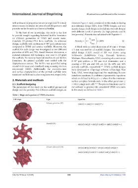
Table 1. Shape and equation of TPMS structures
Cell shape Type Equation
Schwarz primitive (SP) cos( )x + cos()y + cos( )z = c
Gyroid (GY) sin( )cos()x y + sin( )cos()y z + sin( )cos()z x = c
Schwarz diamond (SD) sin( )sin() sin( )x y z + sin() cos( )cos()x y z + cos( )sin() cos( )x y z + coos() cos( )sin()x y z = c
sin( )sin() sin( )x y z + sin() cos( )cos()x y z + cos( )sin() cos( )x y z + coos() cos( )sin()x y z = c
Volume 10 Issue 1 (2024) 326 https://doi.org/10.36922/ijb.1768