
Page 382 - IJB-10-1
P. 382
International Journal of Bioprinting Design of dual-unit porous scaffold
Figure 4. Setting of boundary conditions for finite element simulation of
compression.
3. Results and discussion
3.1. Macroscopic morphology analysis
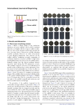
Figure 5 shows a camera photo of the continuous
transition connected scaffolds, which exhibit consistent
diameters and heights with the designed scaffold models.
The top view reveals seamless connections between the
inner and outer layers of the porous scaffold, indicating
excellent continuity. Moreover, no visible deformations
or pore plugging phenomena were observed on the Figure 5. The macro-morphologies of the designed porous scaffold.
scaffold surfaces, confirming successful preparation of
continuous transition connected scaffolds. A slight sticky
powder phenomenon was observed on the scaffold surface, the designed ones because of the gradual decrease in the
primarily arising from the thermal gradient between volume of powder particles on the surface of the scaffolds
successive layers during the SLM preparation process. and the increase in the amount of powder shedding during
This condition caused the adherence of a small amount of the melting process. Based on these previously reported
42
powder to the scaffold, giving it a sticky appearance. Since observations, we confirmed that dual-unit continuous
the amount of adhered powder was minute, the effect on transition porous scaffold was successfully designed and
the mechanical properties of the scaffold was very minimal. prepared in this work.
Figure 6 shows the micro-CT scanning reconstruction Figure 7 shows the SEM images of the prepared porous
images of the scaffolds, which is consistent with the profile scaffolds. It can be seen from Figure 7A, D, F, G, and I
of the porous scaffold depicted in the Figure 5. Detailed that the porous scaffold is covered with a small amount of
micro-CT images show that the connection between the sticky powder, and there are a large number of “dendrites”
two units of the scaffold is smooth and continuous, and at the unit joints of the P combination structure, resulting
there is no deformation and blockage. in a smaller aperture of the P unit as compared to the
The porosities of the scaffolds measured by the designed one. Figure 7E and H depicts the presence of
Archimedes drainage method are presented in Table 4. It unconnected areas in the G-D and D-G porous scaffolds,
can be seen that the porosities of the porous scaffold are which can be attributed to the fusion penetration
basically consistent with the designed porosity, and the phenomenon during the SLM process. This phenomenon
error is within 4%, which is within the permissible range of is caused by the support thickness being smaller than the
sample preparation error. The measured porosity of a small design size, which impacts the mechanical properties
number of samples is smaller than the designed models, of the scaffold to some extent. Thus, it is essential to
because the actual pore size of the sample is smaller than consider the accuracy of processing and the minimum
the design value due to the surface sticky powder and design size while designing the scaffold. 43,44 While sound
the “step effect” during SLM preparation. However, the continuous transition connections were formed in the
41
porosity of most samples is slightly larger than that of P-G, G-P, P-D, and D-P porous scaffolds (Figure 7D, F, G,
Volume 10 Issue 1 (2024) 374 https://doi.org/10.36922/ijb.1263