
Page 385 - IJB-10-1
P. 385
International Journal of Bioprinting Design of dual-unit porous scaffold
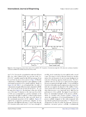
Figure 8. (A–E) Compression stress–strain curves of the scaffolds. (F) Comparison of mechanical properties of the dual-unit continuous transition-
connected scaffolds with scaffolds prepared in previous work.
was P>D>G. It is worth noting that this order was different 94 MPa, which is 36% less than the scaffold with a size of
than the order deduced from our previous work (i.e., 2 mm. The reason is that the decrease of unit size can also
P>G>D), possibly caused by the SLM processing. It can reduce the rod diameter of unit structure, leading to the
45
be seen from the stress–strain curves in Figure 8B that the reduction of bearing capacity of unit structure. The D-G
combination of different unit has a great influence on the scaffolds with the unit size of 1.5 and 2 mm have almost
mechanical properties of the porous scaffolds. Based on the same compressive strength, but the 1.5 mm scaffold has
Figure 8B and Table 5, we summarized that the order of better ductility, indicating that appropriate reduction of the
compression strength of the dual-unit connected scaffolds unit size can improve the ductility of the scaffold. Stress–
was (P-G)>(P-D)>(G-P)>(G-D)>(D-G)>(D-P). As can strain curves of D-G with different porosity in Figure 8E
be seen from Figure 8C, the decrease in the ratio of the show that porosity is an important factor affecting the
area of the outer D structure to the total area from 24/25 performance of the scaffold—the higher the porosity, the
to 9/25 was accompanied by a gradual reduction in the lower the mechanical strength of the porous scaffold—
compression strength of scaffolds, confirming the impact which is consistent with previous reports. Figure 8F
46
of area disparity between the inner and outer layers on shows the comparison of mechanical properties of TC4
the mechanical properties of the scaffolds. Figure 8D porous scaffolds designed in this work compared with
depicts the compression performance diagram of D-G equivalents reported in previous studies. 35,47–50 Based on the
structures with different unit sizes. It can be seen that the comparison, it is clear to us that the dual-unit continuous
D-G structure with a unit size of 1 mm has a strength of transition connected porous scaffolds simultaneously
Volume 10 Issue 1 (2024) 377 https://doi.org/10.36922/ijb.1263