
Page 395 - IJB-10-1
P. 395
International Journal of Bioprinting In situ bioprinting for cartilage repair
method, the defect could be segmented from the image. University Third Medical School and were conducted
By further applying the MATLAB isosurface function, the in adherence with the Guide for the Care and Use of
pixels in the 2D image were linked into triangular facets, Laboratory Animals (A2022008).
and a 3D model of the defect was ultimately generated.
2.6. Statistical analysis
2.5. In vivo experiment All experiments were repeated at least four times, and the
Fifteen adult New Zealand rabbits, weighing 3.5 kg each, results are expressed as mean ± standard deviation. Two-
were used in the in vivo experiments and randomly divided sided, non-paired t-test was used for statistical comparison,
into three groups: blank group, direct implantation group, and the statistical significance was set at P < 0.05.
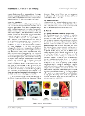
and in situ bioprinting group. First, a lateral parapatellar
incision was made on the articular surface, and a chondral 3. Results
defect with a length of 2 mm and a diameter of 5 mm was 3.1. Results of printing parameter optimization
made at the center of the trochlear groove. In the direct The bioprinting process was optimized by adjusting
implantation group, the cartilage repair ink was cured into the feed rate and printing speed. Figure 3 illustrates the
a cylinder by 405-nm light and then implanted into the optimization results of the printing parameters, where
defect. The blank group was left untreated. With regard to the red area denotes that effective extrusion could not
the in situ bioprinting group, the defect was repaired by be achieved, the yellow area indicates that the feeding of
the parallel manipulator. The detailed surgical procedure materials was insufficient, the blue area indicates that the
is exhibited in Figure 2. After the defect was identified, filament diameter was too thick, the orange area means
the image information of the defect was obtained. that adjacent filament strands were stuck together, and the
Subsequently, a checkerboard was placed above the defect. green area indicates that the extrusion was appropriate.
Through the checkerboard, the relationship between image In general, a high ratio of feed rate to printing speed
pixel distance and actual distance was determined. Next, triggers excessive feed of bioink, which results in an
defect reconstruction and path planning were performed oversized filament. Such an oversized filament may stick
based on the checkerboard and the cartilage defect image. to the adjacent filament, leading to a smaller hole. In
Finally, in situ bioprinting was performed. After completing the case of low ratio, the supplement of the filament will
the corresponding treatment in the different groups, joint become insufficient, making the filament in the scaffold
reduction was performed, and the incision was closed discontinuous. In this study, under a low extrusion
in a layer-by-layer manner. After the disinfection of the multiplier (<0.08), when the printing speed was high,
incision area with 75% alcohol, all rabbits were moved into the material failed to extrude; at lower speeds, a scaffold
their cages. Within 3 days after surgery, penicillin sodium could be formed but with a discontinuous filament. Under
(100,000 U/kg) was injected intramuscularly. All rabbits a high extrusion multiplier, the adjacent filaments were
were allowed to move freely. At 12 weeks after surgery, they stuck together irrespective of the speed. Under a medium
were subjected to batch killing. Imaging examination, gross extrusion multiplier, the diameter of the filament printed
observation, and histological analysis were conducted, and at low speed was too large compared to the scaffold printed
the details can be found in the Supplementary File. at high speed. According to the results, the appropriate
All the animal experiment protocols were approved by printing parameters were 400–560 mm/min with an
the Ethical Committee of Laboratory Animals of Peking extrusion multiplier of 0.09–0.1.
Figure 2. In situ 3D bioprinting process.
Volume 10 Issue 1 (2024) 387 https://doi.org/10.36922/ijb.1437