
Page 394 - IJB-10-1
P. 394
International Journal of Bioprinting In situ bioprinting for cartilage repair
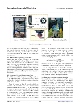
Figure 1. Schematic diagram of in situ bioprinting.
like configuration to produce light in a circular pattern. kit-8 (CCK-8) solution and 100 μL culture medium. After
The ring-like light can prevent the hydrogel near the incubation for 1 h, 110 μL of the liquid was removed
needles from early curing, which would, if not prevented, from each well and placed into a new 96-well plate, and
block the needle, thereby decreasing the printing efficiency the absorbance values were read using a microplate
and accuracy. reader (Thermo, Waltham, USA). The cell viability was
determined using Equation I:
2.2. Optimization of printing parameters
To optimize the printing parameters of the parallel Cellviability(%) As Ab 100 (1)
manipulator, Simplify3D software (USA) was used to slice Ac Ab
a block with dimensions of 10 mm× 10 mm× 2 mm to
layers with a thickness of 0.15 mm. The infill pattern was where As, Ac, and Ab are the optical density (OD) values
rectilinear, and the distance between lines was set at 0.5 of leach liquor of scaffolds, PBS, and blank, respectively.
mm. By adjusting the speed rate and extrusion multiplier, For the cell proliferation and distribution evaluation,
different types of scaffolds were obtained under different 200 μL of cell suspension (5 × 10 mL ) was seeded on the
-1
5
parameters, and their morphology was observed under a scaffold, and CCK-8 and Live/Dead assays were conducted
microscope. to assess the relevant indicators of the cells in scaffolds;
2.3. Biocompatibility of 3D-printed scaffold more details can be found in our previous work. 33
The bioink used in this study was a cartilage repair ink 2.4. Defect segmentation and reconstruction
(TM GMP, SinoBioPrint, China), which consists of gelatin To recognize the defect, a camera was used to capture
methacrylate (GelMA), chondroitin sulfate methacrylate images of the defect, and machine vision was applied
(CSMA), and HAMA. to process the images. A checkerboard was placed on
First, the toxicity of the 3D-printed scaffold was the defect to calibrate the camera using the machine
34
evaluated. A suspension of bone marrow-derived vision toolbox of MATLAB (MathWorks, USA). The
mesenchymal stem cells (BMSCs; 2 × 10 mL ) of a rabbit detectCheckerboardPoints function was used to obtain the
-1
4
in exuberant growth was prepared, and 100 μL of the information of the checkerboard points. Four points were
suspension was seeded in a 96-well plate. After culturing selected to be compared with the actual corresponding
in an incubator for 12 h, 10 μL of scaffold leach liquor or points to determine the relationship between the image
phosphate-buffered saline (PBS) was added to each well. coordinates and the actual ones. By applying this affine
After incubation for 12 h, 24 h, and 48 h, the original relationship, the image of the defect was converted. Through
medium in the well was replaced with 10 μL cell counting grayscale conversion, frequency statistics, and bimodal
Volume 10 Issue 1 (2024) 386 https://doi.org/10.36922/ijb.1437