
Page 429 - IJB-10-1
P. 429
International Journal of Bioprinting Mechanically biomimicking 3D bone model
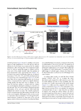
Figure 2. (A) Three-dimensional printing of infill-varied rectangular cuboid structure. (B) Compressive load–displacement curve of an infill-varied
structure. (C) Cross-sectional images of compressed samples at different load states.
several load states (Figure 2B and C). Initially, in the linear the surficial hard part was initially compressed, followed by
region of load–displacement curve, the soft part did not the deformation of the central soft part. The transition of
deform, but the hard part was compressed by the implant deformation was observed at 50% load, where the gradient
indentation. After reaching 50% of the maximum failure of the load–displacement curve changed. This implies that
load, the soft part apparently began to collapse, and the the stiffness for initial deformation is associated with the
outer wall of the sample buckled when the gradient of infill design of surficial region, whereas the failure load
load–displacement curve approached zero (Figure 2B). for final deformation is affected by the infill design of the
To observe the internal deformation behavior, we selected central region.
load states of 25%, 50%, 75%, and 100% and observed the To analyze these results, we used the finite element
corresponding cross-sectional images (Figure 2C). At 25% method (ANSYS 2022. R2) to simulate the strain
load, there was no significant deformation, but the local distribution and compared the infill-varied structure with
surface compressed by the implant was slightly distorted, the infill-uniform structure. In the simulation, the two
causing mostly the hard part only to deform. At 50% structures were locally compressed by the spinal implant
load, the hard part surface in contact with the implant (Figure 3A-i), which was then compared with the entire-
was still dominantly deformed, initiating the distortion of surface compression (Figure 3B-i). The compression in the
the soft part. The 75% load condition produced apparent finite element analysis (FEA) was simulated by applying
deformation of the soft part, and the 100% load fully a downward force of up to 1 mm from the top surface
collapsed the overall structure. The overall compressive of implant while fixing the bottom surface. We used a
behavior showed sequential deformation from the surficial tetrahedral mesh type with a size of 1 mm for efficient and
to the central regions, which agreed with a previous study accurate representation of the model geometry. The FEA
40
on indentation of porous structure. Even though the infill- employed a linear elastic and isotropic material model. The
varied structure contained the hard part at the surficial material parameters such as Young’s modulus and Poisson’s
region, a similar deformation behavior was observed where
Volume 10 Issue 1 (2024) 421 https://doi.org/10.36922/ijb.1067