
Page 434 - IJB-10-1
P. 434
International Journal of Bioprinting Mechanically biomimicking 3D bone model
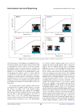
Figure 7. Implant-compression tests for cadaver specimens of Male C7, Female C7, and Female T10.
with PEEK material. The implants were designed to have a the artificial vertebra mimicking Male L4 was used to
conformed interface with the upper surface of the Female compare the patient-specific implant with a commercial
L4 and Male L4 vertebrae (Figure 9). Previous research implant. The two implants did not show a significant
has indicated that the indenter geometry can affect the difference between the corresponding load–displacement
40
indentation resistance in polymeric porous structure. The curves (Figure 10C). The almost flat surface geometry
implant acts as an indenter in the spinal implant system, of the vertebra model meant that the implant interfaces
and designing the implant surface in contact with the of the two implants were similar (Figure 10D), thereby
vertebra body is expected to affect penetration resistance. producing almost identical compressive behavior. Next, the
Subsidence is directly related to the behavior of implant artificial vertebra mimicking Female L4 was created with
penetration into the vertebra and can be evaluated through the infill parameters of [D = 5%, D = 3.5%, vol = 39%],
S
H
S
stiffness and failure load. Implants with higher resistance considering the mechanical properties of Female C7 and
to subsidence are expected to exhibit higher stiffness and Female T10. As shown in Figure 11A, the vertebra–implant
failure load. interface had a highly curved geometry, which produced
The natural cadaver vertebra sample of Male L4 was a significant difference in the design of the commercial
compressed with the patient-specific implant to evaluate and patient-specific implants (Figure 11A). The patient-
the stiffness and failure load of the implant-vertebra specific (Female L4) implant exhibited higher stiffness and
system. These properties were achieved by controlling failure load compared with that of the commercial implant
the infill parameters for artificial vertebra by decreasing (Figure 11B), which is contrary to the results for Male L4-
D from 24% to 12% and increasing D from 24% to specific implant with a flat shape (Figure 10C). This implies
H
S
100% (Figure 10A). The resulting load–displacement that the patient-specific implant has higher resistance to
behavior of the artificial vertebra was similar to that of the subsidence than that of the commercial implant, when the
natural vertebra as shown in Figure 10B. Subsequently, bone–implant interface is a 3D-curved shape. The patient-
specific implant exhibited a uniform stress distribution,
Volume 10 Issue 1 (2024) 426 https://doi.org/10.36922/ijb.1067