
Page 61 - IJB-3-1
P. 61
3D bioprinting of stem cells and polymer/bioactive glass composite scaffolds for bone tissue engineering
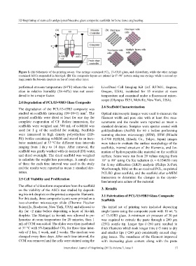
Figure 1. (A) Schematic of the printing set-up. One syringe contained PCL, 13-93B3 glass, and chloroform, while the other syringe
o
o
contained ASCs suspended in Matrigel. (B) The composite layers are printed in 0 –90 pattern using one syringe while a second sy-
ringe prints the bio-ink droplets on top of every other layer.
performed at room temperature (64°F) where the vari- Live/Dead Cell Imaging Kit (ref. R37601, Eugene,
ation in relative humidity (58–60%) was not consi- Oregon, USA), incubated for 15 minutes at room
dered to be a major factor. temperature and examined under a fluorescent micro-
scope (Olympus IX51, Melville, New York, USA).
2.4 Degradation of PCL/13-93B3 Glass Composite
2.6 Scaffold Characterization
The degradation of the PCL/13-93B3 composite was
3
studied on scaffolds measuring (10×10×1) mm . The Optical microscopic images were used to measure the
printed scaffolds were dried at least for one day for filament width and pore size with at least five mea-
complete evaporation of CF. Before immersion, the surements and the results were reported as mean ±
scaffolds were weighed and 300 mL of α-MEM was standard deviation. Samples were sputter coated with
used for 1 g of the scaffold for soaking. Scaffolds gold/palladium (Au/Pd) for 60 s before performing
were immersed in high density polyethylene (HD- scanning electron microscopy (SEM). SEM (Hitachi
PE) bottles containing α-MEM and stored in an incu- S-4700 FESEM, Hitachi Co., Tokyo, Japan) images
bator maintained at 37 °C for different time intervals were taken to evaluate the surface morphology of the
ranging from 1 da y to 14 days. After removal, the scaffolds, internal structure of the filaments, and for-
scaffold was gently washed with de-ionized (DI) water, mation of hydroxyapatite-like material on the scaffold
and dried overnight. The dried scaffold was weighed surface. Scans were run from 2θ values ranging from
to calculate the weight loss percentage. A sample size 10° to 80° using Cu Kα radiation (λ = 0.154056 nm)
of three for each time interval was used in the study for X-ray diffraction (XRD) analysis (Philips X-Pert,
and the results were reported as mean ± standard dev- Westborough, MA) on the as-received PCL, as-printed
iation. PCL/B3 glass scaffold, and the scaffold after α-MEM
2.5 Cell Viability and Proliferation immersion to determine the changes in the crystal-
line/amorphous nature of the material.
The effect of chloroform evaporation from the scaffold
on the viability of the ASCs was studied by deposit- 3. Results
ing bio-ink droplets on the printed composite filaments. 3.1 Fabrication of PCL/13-93B3 Glass Composite
For this study, three composite layers were printed on a Scaffolds
two-chamber microscope slide (Thermo Fischer
Scientific, Rochester, New York, USA) and allowed to The initial set of printing tests included depositing
dry for ~2 mins before depositing a layer of bio-ink single layers using the composite paste with 10 wt. %
droplets. The Matrigel in bio-ink was allowed to po- of 13-93B3 glass. A minimum air pressure of 30 psi
lymerize at room temperature for 20 minutes, then 1 was required to extrude the paste through a 260 μm
mL of CCM was added. The slides were then incubated (25G) nozzle tip. Larger tips (>260 µm) resulted in
at 37 °C with 5% humidified CO 2 for three time inter- thick filaments which took longer time (>5 min) to dry
vals of 2 hrs, 1 week, and 2 weeks. The medium was and smaller tips (<260 µm) consistently caused clog-
changed every three days. After each time interval, the ging issues. The roundness of the filament improved
CCM was removed and the cells were stained using the with increasing glass content along with the paste
International Journal of Bioprinting (2017)–Volume 3, Issue 1 57