
Page 62 - IJB-3-1
P. 62
Caroline Murphy, Krishna Kolan, Wenbin Li, et al.
viscosity. The minimum air pressure required to ex- (12 layers). The scaffold fabricated with C5 paste had
trude the paste increased when glass content was in- enough strength to be safely handled for subsequent
creased from 10 wt. % to 30 wt. %. At higher glass degradation and in vitro assessment.
content (40 wt. % and 50 wt. %), the nozzle clogged SEM images of scaffolds fabricated with C5 paste
during fabrication. Therefore, additional CF (about 1 are shown in Figure 3. Figures 3A and 3B show the
mL) was added to the paste to reduce the viscosity for surface morphology of the filament. Glass particles
clog-free extrusion using the 25G tip. The 13-93B3 are conspicuously absent from the surface of filaments.
glass weight percentage and PCL: CF ratios used to No pores on the filament surface were detected even
make composite pastes are shown in Table 1. The fi- when observed at a 2000× magnification. Figures 3C
nal printing parameters used to fabricate the compo- and 3D show the filament cross-sectional surface.
site scaffolds containing 50 wt. % 13-93B3 glass con- Glass particles dispersed in the PCL matrix can be
tent is also provided in Table 1. seen in the interior. The dissolved PCL in chloroform
encloses the glass particles and surface tension ef-
Table 1. PCL/13-93B3 glass paste compositions and printing fects between the nozzle tip and PCL during extrusion
parameters appear to have caused the presence of only PCL on the
Composite 13-93B3 Glass PCL:CF Final Printing Parameters surface.
Paste # (wt. %) (g to mL) (using C5 paste)
C1 10 5:3 Printing speed – 8 mm/s 3.2 Degradation and Bioactivity of PCL/13-93B3
C2 20 5:3 Dwell time – 2 min Glass Composite
C3 30 5:3 Layer height – 0.1 mm Recent studies suggest that cell culture medium can be
C4 40 5:4 Air pressure – 30 psi used as an alternative to simulated body fluid (SBF) to
C5 50 5:4 Nozzle tip – 260 µm evaluate the bioactivity of the materials, with no sig-
nificant differences in the formation of hydroxyapatite
A filament width of 397±10 μm was measured for (HA) [31] . We studied the degradation of the compo-
scaffolds printed with the C5 paste while average pore site by soaking the scaffolds made with C5 paste in
size is dependent on the filament spacing. A filament α-MEM for 1, 3, 7, and 14 days. The scaffold
spacing of 600 µm provided square pores measuring weight before and after immersion (post drying) was
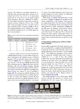
~160 µm (Figure 2A). In comparison, the average recorded at each time interval. No significant weight
pore size was ~350 µm for scaffolds fabricated with loss was observed for 3 days (less than 1%), and the
800 µm filament spacing. Figure 2B shows scaffolds measured weight loss was 10.7±5% at 7 days and
fabricated with 800 µm filament spacing. Warping 23.2±4% at 14 days. As PCL takes a longer time to
was predominant while fabricating scaffolds with C1 degrade, the weight loss measured is due to the ionic
and C2 pastes and this led to difficulty in printing after dissolution of the 13-93B3 borate glass. Formation of
about 8 l ayers; see warped C1 and C2 scaffolds in flower like florets, which typically represent HA-like
Figure 2B. The warpage in scaffolds fabricated with material, was observed on the filament surface as
C3 paste was less pronounced and a scaffold height of shown in Figures 4A and 4B.
0.8 mm (10 layers) was obtained. Overall, the best The energy-dispersive X-ray spectroscopy (EDX)
results were achieved for scaffolds fabricated with C5 analysis indicated the presence of calcium (Ca),
paste as they were successfully printed to 1 mm height phosphorous (P), and oxygen (O) on the reacted
Figure 2. (A) Optical microscopic image showing the pores (~160 µm) in a composite scaffold fabricated with C5 paste. (B) Scaffolds
fabricated with different composite pastes (C1 to C5). The bottom panel shows scaffold warpage with an arrow indicating space be-
tween scaffold and slide. Warpage was minimal in C3/C4 scaffolds and completely absent in C5 scaffolds.
58 International Journal of Bioprinting (2017)–Volume 3, Issue 1