
Page 66 - IJB-3-1
P. 66
Caroline Murphy, Krishna Kolan, Wenbin Li, et al.
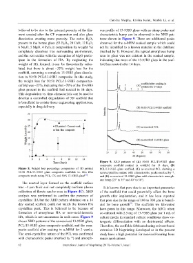
believed to be due to the internal porosity of the fila- ous profile of 13-93B3 glass with no sharp peaks and
ment created after the CF evaporation and also glass characteristic hump can be observed in the XRD pat-
dissolution creating more porosity. The entire B 2O 3 terns shown in Figure 9. There are additional peaks
present in the borate glass (53 B 2O 3, 20 CaO, 12 K 2O, observed for the α-MEM soaked sample which could
6 Na 2O, 5 MgO, 4 P 2O 5 in composition by weight %) not be identified to a known material in the database
completely dissolves into surrounding environment, (marked by †). However, the typical amorphous hump
and the rest oxides with the exception of MgO partic- seen in glass was not existent in the soaked sample,
ipate in the formation of HA. By neglecting the indicating that most of the 13-93B3 glass in the scaf-
weight of HA formed, it can be theoretically calcu- fold has reacted after 14 days.
lated that there is about ~35% weight loss for the
scaffold, assuming a complete 13-93B3 glass dissolu-
tion in 50:50 PCL/13-93B3 composite. In this study,
the weight loss for 50:50 PCL/13-93B3 composites-
caffold was ~23%, indicating that ~70% of the 13-93B3
glass present in the scaffold had reacted in 14 days.
This degradation vs. time characteristic can be used to
develop a controlled degradation of 3D scaffold that
is beneficial in certain tissue engineering applications,
especially in drug delivery.
Figure 9. XRD patterns of (A) 50:50 PCL/13-93B3 glass
composite scaffold soaked in α-MEM for 14 days, (B)
Figure 8. Weight loss percentage comparison of 3D printed PCL/13-93B3 glass scaffold, (C) as-received PCL showing a
50:50 PCL/13-93B3 glass composite scaffolds vs. thin film semi-crystalline nature with characteristic peaks marked by *,
composite made using PCL, CF, and 50% 13-93B3 glass [35] . and (D) as-received 13-93B3 glass with characteristic amorph-
ous hump (25° to 35° and 40° to 50°).
The reacted layer formed on the scaffold surface
was ~1 µm thick and not completely uniform (dense It is known that pore size is an important parameter
collection of florets can be seen in Figure 4C). XRD of the scaffold that could potentially affect the bone
analysis was performed to confirm the presence of growth after implantation, and it has been reported
crystalline HA but the XRD pattern obtained on a 14 that pore size in the range of 100 to 300 µm is benefi-
[9]
day soaked scaffold could not match the known HA cial for bone growth . The scaffolds we fabricated
crystalline peak. This is believed to be because of have pores in this range. Moreover, the ASCs when
formation of amorphous HA or non-stoichiometric co-cultured with 2.5 mg of 13-93B3 glass per 1 mL of
HA, which is not uncommon in such cases. Figure 9 culture media in standard culture conditions show os-
shows XRD patterns of the as-received 13-93B3 glass, teogenic differentiation with no detrimental effects.
PCL/13-93B3 glass composite scaffold, and the com- Therefore, the scaffolds fabricated using solvent-based
posite scaffold after soaking in α-MEM for 2 weeks. extrusion 3D bioprinting developed as in the present
The semi-crystalline nature of the PCL was confirmed study have a high potential for non-load-bearing bone
with characteristic peaks (marked by *) and amorph- repair applications.
62 International Journal of Bioprinting (2017)–Volume 3, Issue 1