
Page 34 - IJB-3-2
P. 34
A new design of an electrospinning apparatus for tissue engineering applications
Several laboratory-type and industrial scale electro-
spinning systems are commercially available [11–13] .
How ever, laboratory-type systems are still relatively
expensive, and, due to its low complexity, most research
laboratories assembled their own systems [14–16] .
The solution electrospinning process is influenced
by several parameters, such as: solution parameters
(e.g., viscosity, polymer concentration, solvent type),
processing parameters (e.g., flow rate, distance between
needle and collector, voltage, type of collector) and
ambient conditions (e.g., temperature and humidity) .
[17]
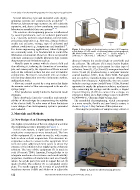
For tissue engineering applications, where hydrogels Figure 1. New design of electrospinning system. (A) Computer-
are commonly used, it is fundamental to control the aided design (CAD) model of electrospinning system proposed;
(B) Main components:1 – acrylic box, 2 – acrylic support, 3 –
fabrication environment. However, this is not possible cork base, 4 – teflon rod, 5 – collector, 6 – needle support.
with most commercial available laboratory-type systems
that present several limitations such as: distance between the needle (single or core/shell) and
- Metallic parts in contact with the electric field and the collector. The collector (5) is static but its fixation
thus affecting it, inducing the formation of secondary system allows its easy replacement by other type of
jets, and consequently, the deposition of fibers was not collectors. Items (1), (2), (4) and (5) were purchased and
only on the collector surface but also over all metallic items (3) and (6) produced using a computer numeric
components. Moreover, non-stable jets can induce control machine (CNC, from INAUTOM, Portugal)
solvent drop deposition over the electrospun meshes, and an additive manufacturing system (Dimension
making them toxic; machine from Stratasys). Additionally, the new system
- Flow rate control exerted by a step motor that limits includes a syringe pump (model Pump 11Elite, Harvard
the accurate control of flow rate compared to the use of a apparatus) to supply the polymeric solution, a polymeric
syringe pump; tube connecting the syringe and the needle, a Liquid
- Fiber production mostly limited to horizontal mode Crystal Display (LCD) to control the voltage, an
strategies. emergency button and a high voltage source (model PS/
These drawbacks limit the versatility and reprodu- MJ30P0400-11, Glassman High Voltage, Inc).
cibility of this technique by compromising the stability The assembled electrospinning, which corresponds
of the electric field. To solve some of these limitations to a more versatile, flexible and user-friendly system, is
a new design of an electrospinning system is presented shown in Figure 2. Key features of this system are:
and evaluated. - Allowing the preparation of samples using vertical or
2. Materials and Methods
2.1 New Design of an Electrospinning System
The digital representation of the new design of a solution
electrospinning system is presented in Figure 1.
In this new system, a significant number of non-
conductive components were introduced. The box
of the equipment (1) is made in acrylic, with a main
hole to allow solvent evaporation. This structure in-
corporates a door to access to the equipment inner
part and some additional entry spots to allow the
entrance of the infusion tubes supplying the polymeric
solution. The base of the equipment (3) is made in
cork (Corecork TB40, Amorim, Portugal) due to its
adequate mechanical resistance and machinability
properties, insulation characteristics and eco-friendly
nature. An acrylic part (2) is used to support the rod (4)
made of teflon. The collector (5) is a grounded copper
plate. The needle support (6) is made of acrylonitrile
butadiene styrene (ABS) and slides on to adjust the Figure 2. Assembled electrospinning apparatus
122 International Journal of Bioprinting (2017)–Volume 3, Issue 2