
Page 291 - IJB-10-3
P. 291
International Journal of Bioprinting Design and optimization of 3DP bioscaffolds
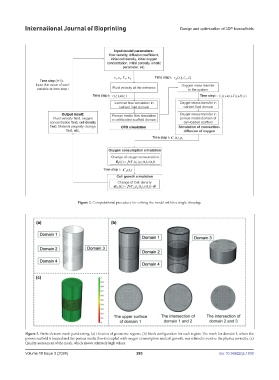
Figure 2. Computational procedure for solving the model within a single timestep.
Figure 3. Finite element mesh partitioning. (a) Division of geometric regions. (b) Mesh configuration for each region. The mesh for domain 3, where the
porous scaffold is located and the porous media flow is coupled with oxygen consumption and cell growth, was refined to resolve the physics correctly. (c)
Quality assessment of the mesh, which shows relatively high values.
Volume 10 Issue 3 (2024) 283 doi: 10.36922/ijb.1838