
Page 183 - IJB-10-4
P. 183
International Journal of Bioprinting Effects of structure on the interbody cage
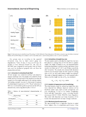
Figure 2. Schematic of porous interbody cage 3D printing. (A) Melt differential 3D printing system. (B) Schemes of porous cage with distinct structural
features: 60% and 40% filling rate in columns A and B, respectively, and 1, 2, and 4 crossing layers in rows I, II, and III, respectively.
Five groups were set according to the expected 2.3.2. Calculation of weight loss rate
immersion time, that is, blank control group (no The test samples used to calculate the weight loss rate were
degradation), 7 days, 14 days, 21 days, and 28 days. Six first placed in a drying oven at 35°C for 24 h to constant
samples of every structural feature (AI, AII, AIII, BI, weight. The weight of samples, as W , was measured before
0
BII, BIII) were prepared for each group, three of which immersion degradation (starting moment), and labeled. Three
were used for mechanical property tests and three for samples were taken out at 7, 14, 21, and 28 days, respectively,
physicochemical tests. after immersion. The samples were cleaned with deionized
water for 20 min ultrasonically, and then placed in a drying
2.3.1. Immersion in simulated body fluid oven at 35°C for 24 h until constant weight was achieved.
All test samples were ultraviolet-sterilized and placed in The weight of degraded samples, as W, was measured with a
t
separate centrifuge tubes. The samples were soaked in 10 mL balance, and the weight loss rate, as W , was calculated.
of SBF, and the containers were firmly closed to ensure that the loss
samples were thoroughly submerged in the soaking solution. W = (W – W) / W × 100% (I)
0
loss
t
0
The soaking container was put in a thermostat to maintain
the physiological temperature at 37°C. The pH alterations of 2.3.3. Analysis of appearance and morphology
SBF were monitored during the test period, and the SBF was The dried samples, used for calculating weight loss rate,
adjusted every week to regulate the pH at 7.4 ± 0.3. were observed for different structural features of the
interbody fusion cages, such as beam arrangement and
Table 1. Scheme of meso-structural characterization of pore morphology, as well as the surface morphology
the cages before and after degradation, using a scanning electron
Fill percentage 60% 40% microscope (MAIA 3 XMU, TESCAN, Czech Republic).
The actual hole diameters and beam diameters of the
Crossing layers fusion were measured with the help of Image-J software.
1 layer AI BI 2.3.4. Mechanical performance test
2 layers AII BII The cage generally serves a supportive function in spinal
4 layers AIII BIII fusion surgery; thus, its compression performance is key
Volume 10 Issue 4 (2024) 175 doi: 10.36922/ijb.1996