
Page 502 - IJB-10-4
P. 502
International Journal of Bioprinting 3D-printed variable stiffness scaffolds
2.2. Scaffold design
To develop an appropriate 3D architecture for the meniscus
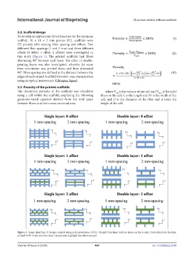
scaffold, 10 × 10 × 2 mm porous PCL scaffolds were (I)
3D printed with varying fiber spacing and offsets. Two
different fiber spacings (1 and 2 mm) and three different
offsets (0 offset, 1 offset, 2 offsets) were investigated in (II)
this study (Figure 1). The printed scaffolds had fibers
alternating 90° between each layer. The effect of double-
printing layers was also investigated, whereby the same
fiber orientation was printed twice and then alternated
90°. Fiber spacing was defined as the distance between the (III)
edges of each strand. Scaffold formation was characterized
using an optical microscope (Olympus, Japan).
2.3. Porosity of the printed scaffolds
The theoretical porosity of the scaffolds was calculated where V is the volume of one cell and V is the solid
cell
fiber
using a cell within the scaffold, employing the following fibers in the cell; L is the length and W is the width of the
geometry-based equation derived from the void space cell; and D is the diameter of the fiber and is twice the
between fibers and their cross-sectional area: height of the cell.
Figure 1. Image depicting 12 designs printed using polycaprolactone (PCL). Straight blue lines indicate layers on the x-axis. Circles illustrate the layer
printed at 90° to the previous layer. Green layers highlight the offsets present.
Volume 10 Issue 4 (2024) 494 doi: 10.36922/ijb.3784