
Page 561 - IJB-10-4
P. 561
International Journal of Bioprinting Light-based muscle bioprinting with bioglass
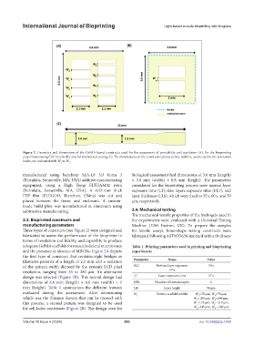
Figure 2. Geometry and dimensions of the GelMA-based constructs used for the assessment of printability and resolution (A), for the bioprinting
experiments using C2C12 cells (B), and for mechanical testing (C). The thin features of the constructs (characteristic widths), used to define the resolution
limits, are indicated with W to W .
a e
manufactured using benchtop SLA-LF 3D Form 3 biological assessment had dimensions of 3.6 mm (length)
(Formlabs, Somerville, MA, USA) additive manufacturing × 3.6 mm (width) × 0.8 mm (height). The parameters
equipment, using a High Temp FLTHAM02 resin considered for the bioprinting process were normal layer
(Formlabs, Somerville, MA, USA). A 0.15-mm thick exposure time (LT), first layers exposure time (FLT), and
FEP film (ELEGOO, Shenzhen, China) was cut and layer thickness (LTh), which were fixed to 35 s, 60 s, and 50
placed between the frame and enclosure. A custom- μm, respectively.
made build plate was manufactured in aluminum using
subtractive manufacturing. 2.4. Mechanical testing
The mechanical tensile properties of the hydrogels used in
2.3. Bioprinted constructs and the experiments were evaluated with a Universal Testing
manufacturing parameters Machine (3365 Instron, UK). To prepare the samples
Three types of constructs (see Figure 2) were designed and for tensile assays, bone-shape testing constructs were
fabricated to assess the performance of the bioprinter in fabricated following ASTM D638 standard with a thickness
terms of resolution and fidelity, and capability to produce
adequate GelMA scaffolds for musculoskeletal microtissues Table 1. Printing parameters used in printing and bioprinting
and the presence or absence of MBGNs. Figure 2A depicts experiments
the first type of construct that contains eight bridges or
filaments patterns of a length of 2.1 mm and a variation Parameter Name Value
of the pattern width dictated by the system’s LCD pixel BLT Bottom layer exposure 50 s
resolution, ranging from 35 to 280 μm. An alternative time
design was selected (Figure 2B). This second design had LT Layer exposure time 37 s
dimensions of 6.6 mm (length) × 6.6 mm (width) × 1 NBL Number of bottom layers 2
mm (height). Table 1 summarizes the different features LH Layer height 50 µm
evaluated during the assessment. After determining W Pattern scaffold widths W =35 µm, W =70 µm,
a
b
which was the thinnest feature that can be created with x W =105 µm, W =140 µm,
d
c
this process, a second pattern was designed to be used W =175 µm, W = 210 µm,
f
e
for cell-laden constructs (Figure 2B). The design used for W =245 µm, W = 280 µm
h
g
Volume 10 Issue 4 (2024) 553 doi: 10.36922/ijb.1830