
Page 68 - IJB-5-1
P. 68
Mechanisms and modeling of electrohydrodynamic phenomena
Table 2. A summary of theoretical models for three phenomena under different assumptions, and their advantages and disadvantages
Phenomenon Theories or models Assumption and conditions Advantages Disadvantages
Conical meniscus Taylor Semi-vertical angle of cone is Obtaining critical voltage Semi-angle is not always
electrohydrostatic 49.3°; Pressure is zero; Neglected value for jet emission from the 49.3°; Approximate 10%
model (Taylor cone) weight of the liquid cone tip of the cone difference from the critical
voltage of experiment
Cone-jet transition Leaky dielectric model; Penetration of electric field lines Described operating diagram Only for leaky dielectric
Surface couple model into liquid; Appearance of surface of cone-jet for inks with material and stable cone-jet
electric charges partial electrical conductivity mode; Complexity in a
mathematical method
Stability of a long and One-dimensional model Tangential stress caused by electric Identified three instability Inaccurate in low viscosity
slender jet field must be much smaller than the modes based on electric and/or imperfect conductor
radial viscous stress; Wavelength field strength; Represented jet
of the perturbation is much smaller operating diagram of varicose
than the characteristic decay length and whipping instability
of the jet thresholds
A B
C
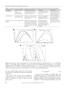
Figure 6. (A) Growth rate σ versus the wavenumber k for a jet with b (distance between two radial electrodes) >>1, χ = 0.6, C (Ohnesorge
number) = 1, and β (liquid relative permittivity) = 2 and several values of the relaxation parameter α; (B) Growth rate σ versus the
wavenumber k for a jet with different values of the Ohnesorge number C (b >>1, α=1, β=1, χ=0.6). (C) Growth rate σ versus the wave
number k for a jet with b>>1 and b=2. The other parameters are fixed at C=1, α=1, and β=2. Several values of the electrification number χ
are plotted [81]. Adapted by permission from Jose Lopez-Herrera et al. (2005) under the AIP Publishing LLC.
and may promote longer liquid jets with moderate ργ . 05 (30)
viscosity in the non-whipping jet regime for an imperfect C = µ /( r)
conductor . Viscosity does not change the stability limits, but
[81]
The effects of the viscosity can be reflected by it lowers the growth rate of any perturbation. The most
comparing growth curves having different Ohnesorge unstable wavelength becomes longer with an increase of
numbers, C, defined as a ratio of viscous forces to Ohnesorge number in Figure 6B, whereas the growth rate
capillary forces, decreases . A narrow interfacial boundary layer with
[81]
14 International Journal of Bioprinting (2019)–Volume 5, Issue 1