Page 93 - IJB-5-1
P. 93

Designs and Applications of EHD 3D Printing

                         A                                               B


                         C                                  D


                         E                                  F


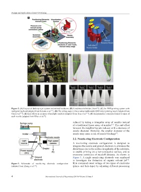
           Figure 2. (A) Layout of desktop e-jet system and related hardware. (B) A multinozzle holder (from ). (C) An EHD printing system with
                                                                                   [10]
           multiprinting head (adapted from Sutanto et al. ). (D) The jetting angle in linear array multinozzle EHD inkjet printing head (Adapted from
                                            [11]
           Choi et al. ). (E) End effects in an array of multiple emitters (adapted from Tran et al. ). (F) Axisymmetric cone-jets formed at apex of
                                                                          [15]
                  [12]
           each nozzle (adapted from Khan et al. ).
                                      [7]
                                                               reduced by taking a triangular array of nozzles instead
                                                               of a traditional linear array of nozzles . The end effect
                                                                                               [12]
                                                               between the neighboring jets reduces with a decrease of
                                                               nozzle  diameter. However, the  smaller  diameter  of the
                                                               nozzle may cause a risk of nozzle blockage .
                                                                                                   [7]
                                                               2.2. Nozzle-ring Electrode Configuration
                                                               A  nozzle-ring  electrode  configuration  is designed  to
                                                               integrate the nozzle and ground electrode to eliminate the
                                                               disturbance due to the surface irregularity of the substrate,
                                                               to  enable  printing  on  a  non-conductive  surface,  and  to
                                                               overcome restriction of standoff distance. As shown in
                                                               Figure 3, A  single  nozzle-ring  electrode  was  employed
                                                               to investigate the formation of organic solvent jet .
                                                                                                            [18]
           Figure 3.  Schematic  of  nozzle-ring  electrode  configuration   Kim compared onset voltage of two types of electrodes
                              [18]
           (adapted from Zhang et al. ).                       (plane- and hole-type) by adjusting different processing


           4                           International Journal of Bioprinting (2019)–Volume 5, Issue 1
   88   89   90   91   92   93   94   95   96   97   98