
Page 92 - IJB-5-1
P. 92
Gao and Zhou
A B holder. Since the weight of print heads and their distance
from the axis of rotation produce a large rotational
inertia, a transmission with a high gear ratio is required
to couple with the motor to provide a sufficient large
torque . However, the stick-slip resistance coming
[11]
from the gear reduces the accuracy of overlay in drop-
on-demand. To offset this undesired effect, a two-
step macro/micro-positioning method is employed to
achieve micropositioning accuracy. The function of the
macropositioning algorithm is to bring the nozzle into
C D the camera view field, and duty of the micropositioning
controller is to apply precise servo level control to locate
nozzle position with respect to the substrate .
[11]
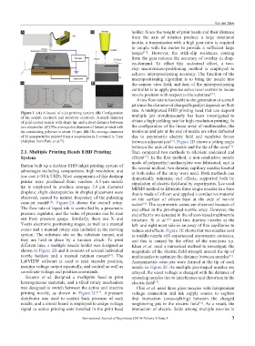
A low flow rate is favorable to the generation of a small
jet since the diameter of charged liquid jet depends on flow
rate. A multiplexed EHD printing head that can deposit
Figure 1. (A) A layout of e-jet printing system. (B) Configuration
of the nozzle electrode and substrate electrode. A small diameter multiple jets simultaneously has been investigated to
of gold-coated nozzle with sharp tip, and a short distance between obtain a high yielding rate for high-resolution printing. In
two electrodes. (C) The average dot diameter of letters printed with the configuration of the linear array of multinozzles, the
the conducting polymer is about 10 µm. (D) The average diameter meniscus and jets at the end of nozzle are often deflected
of Si nanoparticles printed from a suspension in 1-octanol is 3 nm due to asymmetric electric field and repulsive forces
(Adapted from Park et al. ). between adjacent jets . Figure 2D shows a jetting angle
[9]
[12]
between the axis of the nozzle and the tip of the cone .
[12]
2.1. Multiple Printing Heads EHD Printing Tran compared two methods to alleviate undesired end
System effects . In the first method, a non-conductive nozzle
[13]
made of polymethyl methacrylate was fabricated, and in
Barton built up a desktop EHD inkjet printing system of the second method, two dummy capillary nozzles located
advantages including compactness, high resolution, and at both sides of the array were used. Both methods can
low cost (<50 k USD). Most components of this desktop dramatically minimize end effects, supported both by
printer were purchased from vendors. A 5-µm nozzle simulation of electric field and by experiments. Lee used
tip is employed to produce average 2.8 µm diameter MEMS method to fabricate three single nozzles in a base
droplets; slight discrepancies in droplet placement were that is made of silicon and applied a conductive material
observed, caused by natural frequency of the pulsating on the surface of silicon base at the side of nozzle
cone-jet model . Figure 2A shows the overall setup. outlet . The asymmetric cones are observed because of
[10]
[14]
The flow rate of liquid ink is controlled by a pneumatic end effect in the pin-shaped nozzle array. However, the
pressure regulator, and the value of pressure can be read end effect is not detected in the silicon-based multinozzle
out from pressure gauge. Similarly, there are X- and structure. Si et al. used two dummy nozzles at the
[15]
Y-axis electronic positioning stages, as well as a manual left- and right-most side in an array of five capillaries to
z-axis and a manual rotary axis included in the moving reduce end effects. Figure 2E shows that two nozzles next
system. The substrate sits on the substrate mount, and to middle nozzle still experienced asymmetric emission,
they are held in place by a vacuum chuck. To print and this is caused by the effect of the meniscus tip.
different inks, a multiple nozzle holder was designed as Khan et al. used a numerical method to investigate the
shown in Figure 2B and it consists of several individual magnitude of the electric field strength around the tip of
nozzle holders and a manual rotation mount . The multinozzles to optimize the distance between nozzles .
[10]
[16]
LabVIEW software is used to read encoder position, Axisymmetric cone-jets were formed at the tip of each
monitor voltage output repeatedly, and control as well as nozzle in Figure 2F. As multiple pin-shaped nozzles are
coordinate voltage and position commands. arrayed, the onset voltage is changed with the distance of
Sutanto et al. designed a multiprint head to print operating nozzles due to interference and distortion in the
heterogeneous materials, and a tilted rotary mechanism electric field .
[17]
was designed to switch between the active and inactive Choi et al. used three glass nozzles with independent
printing nozzle, as shown in Figure 2C . A pressure voltage connection and ink supply source to explore
[11]
distributor was used to control back pressure of each that interaction (cross-talking) between the charged
nozzle, and a circuit board is employed to assign voltage neighboring jets in the electric field . As a result, the
[12]
signal to active printing unit installed in the print head interaction of electric fields among multiple nozzles is
International Journal of Bioprinting (2019)–Volume 5, Issue 1 3