
Page 105 - IJB-5-2
P. 105
Lenoir L, et al.
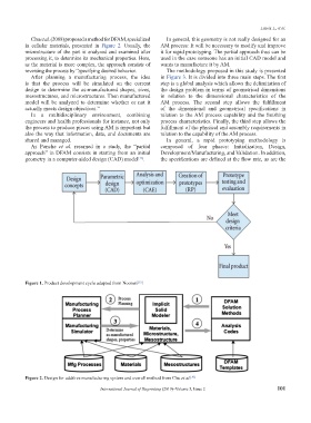
Chu et al. (2008) proposed a method for DFAM, specialized In general, this geometry is not really designed for an
in cellular materials, presented in Figure 2. Usually, the AM process: It will be necessary to modify and improve
microstructure of the part is analyzed and examined after it for rapid prototyping. The partial approach thus can be
processing it, to determine its mechanical properties. Here, used in the case someone has an initial CAD model and
as the material is more complex, the approach consists of wants to manufacture it by AM.
reversing the process by “specifying desired behavior. The methodology proposed in this study is presented
After planning a manufacturing process, the idea in Figure 3. It is divided into three main steps. The first
is that the process will be simulated on the current step is a global analysis which allows the delimitation of
design to determine the as-manufactured shapes, sizes, the design problem in terms of geometrical dimensions
mesostructures, and microstructures. Then manufactured in relation to the dimensional characteristics of the
model will be analyzed to determine whether or not it AM process. The second step allows the fulfillment
actually meets design objectives.” of the dimensional and geometrical specifications in
In a multidisciplinary environment, combining relation to the AM process capability and the finishing
engineers and health professionals for instance, not only process characteristics. Finally, the third step allows the
the process to produce pieces using AM is important but fulfillment of the physical and assembly requirements in
also the way that information, data, and documents are relation to the capability of the AM process.
shared and managed. In general, a rapid prototyping methodology is
As Ponche et al. resumed in a study, the “partial composed of four phases: Initialization, Design,
approach” in DFAM consists in starting from an initial Development/Manufacturing, and Validation. In addition,
geometry in a computer-aided design (CAD) model . the specifications are defined at the flow rate, as are the
[16]
Figure 1. Product development cycle adapted from Noorani .
[15]
Figure 2. Design for additive manufacturing system and overall method from Chu et al. [10]
International Journal of Bioprinting (2019)–Volume 5, Issue 2 101