
Page 109 - IJB-5-2
P. 109
Lenoir L, et al.
Figure 5. Proposed method additive manufacturing-Biopart by Lenoir et al. [23]
addresses the body’s vessels, arteries, and veins, often A B
better visualized after injection, of a product .
[25]
The focus is made on Step III “design and development”:
1. Idea of simplified geometry
The carotid geometry have a very complex form
that is why it bring back to a simplified form. The
complex geometry is changed in a tube of 50 mm
length and 4 mm internal diameter. With each side
connectors for the pump (Figure 7).
The simplification of the model has been established
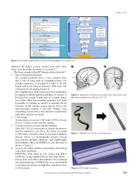
by engineers and biological researchers. It consists of Figure 6. Branches of the internal carotid artery (A) lateral view
bringing the complex model back to a simple shape, (B) anteroposterior view (PEACE 2017) .
[24]
here a tube. Thus, this simplified geometry will make
it possible to validate as quickly as possible all the
elements on the cellular culture part as well as the
manufacturing method of the tube. Finally, once
everything is approved, a new iteration is performed
with more complex geometry.
2. CAD design
Achievements of several CAD with CATIA software
(Figure 8) show a half-mold for casting.
3. Criteria related to process and the material
After the CAD, it is necessary to choose the process
and the material to use. Here, the molds are made
in AM with a material called acrylonitrile butadiene Figure 7. Simplification of the carotid geometry.
styrene, which is a thermoplastic polymer having
good impact strength, relatively rigid, lightweight,
and moldable. Then, the PDMS was cast; the result is
shown in Figure 9.
4. In vitro cell-culture testing on prototypes and testing
under flow conditions
PDMS has been tested in cell culture and inflow
conditions, using a pump that can send large flows.
During flow cell culture development, the prototype
and manufacturing of PDMS tube were ameliorated
to optimize la perfusion at high flow and observation
on microscopy. Figure 8. Half-mold for casting.
International Journal of Bioprinting (2019)–Volume 5, Issue 2 105